
Mechanics of Materials (MindTap Course List)
9th Edition
ISBN: 9781337093347
Author: Barry J. Goodno, James M. Gere
Publisher: Cengage Learning
expand_more
expand_more
format_list_bulleted
Concept explainers
Videos
Textbook Question
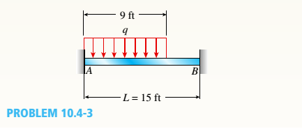
Chapter 10, Problem 10.4.3P
A fixed-end beam AB supports a uniform load of intensity q = 75 lb/ft acting over part of the span. Assume that EI = 300kip-ft2.
- Calculate the reactions at A and B.
Expert Solution & Answer

Trending nowThis is a popular solution!

Students have asked these similar questions
3. Two beams are supported as shown in the diagram below, each 150mm x 200mm x 6 meters. Beam CD is a
cantilever beam carrying a uniformly distributed load of 6 KN/m freely supported on beam AB. Beam AB is
freely supported on each ends. E = 13.8 GPa for both beam. Neglect the weight of the beam.
a. Compute the reaction at D.
b. Compute the deflection at D.
c. Compute the bending stress of beam CD.
6 ka lm
бт
6m
6m
USE THREE MOMENT EQUATION
Calculate the support reaction at A and B for the beam shown in the figure below.
Take F= 570 N.
F
A
B
3M
1M
Ay
By
Reaction force at point B
By=
N.
Reaction force at point A
Ay
N.
Chapter 10 Solutions
Mechanics of Materials (MindTap Course List)
Ch. 10 - A propped cantilever steel beam is constructed...Ch. 10 - A fixed-end b earn is subjected to a point load at...Ch. 10 - A propped cantilever beam AB of a length L is...Ch. 10 - A fixed-end beam AB of a length L supports a...Ch. 10 - A cantilever beam AB of a length L has a fixed...Ch. 10 - A cantilever beam of a length L and loaded by a...Ch. 10 - A cantilever beam has a length L and is loaded by...Ch. 10 - A propped cantilever beam of a length L is loaded...Ch. 10 - A propped cantilever beam of a length L is loaded...Ch. 10 - A fixed-end beam of a length L is loaded by a...
Ch. 10 - A fixed-end b earn of a length L is loaded by a...Ch. 10 - A fixed-end beam of a length L is loaded by...Ch. 10 - A counterclockwise moment M0acts at the midpoint...Ch. 10 - A propped cantilever beam of a length L is loaded...Ch. 10 - A propped cantilever beam is subjected to uniform...Ch. 10 - Repeat Problem 10.3-15 using L = 3.5 m, max = 3...Ch. 10 - A two-span, continuous wood girder (E = 1700 ksi)...Ch. 10 - A fixed-end beam AB carries point load P acting at...Ch. 10 - A fixed-end beam AB supports a uniform load of...Ch. 10 - -4-4 A cantilever beam is supported at B by cable...Ch. 10 - A propped cantilever beam AB of a length L carries...Ch. 10 - A beam with a sliding support at B is loaded by a...Ch. 10 - A propped cantilever beam of a length 2L with a...Ch. 10 - The continuous frame ABC has a pin support at /l,...Ch. 10 - The continuous frame ABC has a pin support at A,...Ch. 10 - Beam AB has a pin support at A and a roller...Ch. 10 - The continuous frame ABCD has a pin support at B:...Ch. 10 - Two flat beams AB and CD, lying in horizontal...Ch. 10 - -4-13 A propped cantilever beam of a length 2L is...Ch. 10 - A propped cantilever beam of a length 2L is loaded...Ch. 10 - Determine the fixed-end moments (MAand MB) and...Ch. 10 - A continuous beam ABC wit h two unequal spans, one...Ch. 10 - Beam ABC is fixed at support A and rests (at point...Ch. 10 - A propped cantilever beam has flexural rigidity EI...Ch. 10 - A triangularly distributed 1oad with a maximum...Ch. 10 - A fixed-end beam is loaded by a uniform load q =...Ch. 10 - Uniform load q = 10 lb/ft acts over part of the...Ch. 10 - A propped cantilever beam with a length L = 4 m is...Ch. 10 - A cant i levé r b ea m i s supported by a tie rod...Ch. 10 - The figure shows a nonprismatic, propped...Ch. 10 - A beam ABC is fixed at end A and supported by beam...Ch. 10 - A three-span continuous beam A BCD with three...Ch. 10 - A beam rests on supports at A and B and is loaded...Ch. 10 - A propped cantilever beam is subjected to two...Ch. 10 - A propped cantilever beam is loaded by a...Ch. 10 - A fixed-end beam AB of a length L is subjected to...Ch. 10 - A temporary wood flume serving as a channel for...Ch. 10 - Two identical, simply supported beams AB and CD...Ch. 10 - The cantilever beam AB shown in the figure is an...Ch. 10 - The beam AB shown in the figure is simply...Ch. 10 - The continuous frame ABC has a fixed support at A,...Ch. 10 - The continuous frame ABC has a pinned support at...Ch. 10 - A wide-flange beam ABC rests on three identical...Ch. 10 - A fixed-end beam AB of a length L is subjected to...Ch. 10 - A beam supporting a uniform load of intensity q...Ch. 10 - A thin steel beam AB used in conjunction with an...Ch. 10 - Find an expression for required moment MA(in terms...Ch. 10 - Repeat Problem 10.4-41 for the loading shown in...Ch. 10 - A propped cantilever beam is loaded by two...Ch. 10 - A cable CD of a length H is attached to the third...Ch. 10 - A propped cantilever beam, fixed at the left-hand...Ch. 10 - Solve t he preceding problem by integrating the...Ch. 10 - A two-span beam with spans of lengths L and L/3 is...Ch. 10 - Solve the preceding problem by integrating the...Ch. 10 - Assume that the deflected shape of a beam AB with...Ch. 10 - (a) A simple beam AB with length L and height h...
Knowledge Booster


Learn more about
Need a deep-dive on the concept behind this application? Look no further. Learn more about this topic, mechanical-engineering and related others by exploring similar questions and additional content below.Similar questions
- A fixed-end beam AB of a length L is subjected to a uniform load of intensity q acting over the middle region of the beam (sec figure). Obtain a formula for the fixed-end moments MAand MBin terms of the load q, the length L, and the length h of the loaded part of the beam. Plot a graph of the fixed-end moment MAversus the length b of the loaded part of the beam. For convenience, plot the graph in the following nondimensional form: MAqL2/l2versusbL with the ratio b/L varying between its extreme values of 0 and 1. (c) For the special case in which ù = h = L/3, draw the shear-force and bending-moment diagrams for the beam, labeling all critical ordinates.arrow_forwardCantilever beam AB carries an upward uniform load of intensity q1from x = 0 to L/2 (see Fig. a) and a downward uniform load of intensity q from x = L/2 to L. Find q1in terms of q if the resulting moment at A is zero. Draw V and M diagrams for the case of both q and qtas applied loadings. Repeat part (a) for the case of an upward triangularly distributed load with peak intensity q0(see Fig. b). For part (b), find q0, instead of q1arrow_forwardFind expressions for shear force V and moment M at v = L/2 of beam AB in structure (a). Express V and M in terms of peak load intensity q0and beam length variable L. Repeat for structure (b) but find Fand M at m id-span of member BC.arrow_forward
- Parvinbhaiarrow_forwardFor the statically indeterminate beam shown in Figure 3, EI is constant. Assume 1, 2, and 3 arerollers and 4 is pinned. Take w = 5.x kN/m. Using the stiffness method, determine the momentsand reactions at each support x=9arrow_forwardGiven the simple beam as shown below. Determine the following: 100 N/m 30 N/m A 2 m B 7m mum. 2m D The External Reaction at Point B. The External Reaction at Point C.arrow_forward
- de The beam shown supports a load that varies uniformly from 250 N/m at the left end to 0 N/m at the right end. The lengths of the beam segments are d₁=2 m, d₂ = 2 m, and d₂ = 8 m. Reactions Determine the reactions at pin A and roller C. Let positive values indicate upward forces. A= C= Internal Load Determine the internal shear and bending moment at a section passing through point D. Use the standard convention for the meaning of positive shears and bending moments. VD= Mp=arrow_forwardPlease also find the FBD in the problemarrow_forward3. Determine the displacement and slope (i.e. 0) at the load point for the stepped beam shown in the following figure. Also determine the reaction forces and moments. Each element has E = 200 GPa. The area moment of inertia are given as I₁ = 1.25 × 105 mm4, and 2 = 4 x 104 mm. Clearly show the elemental stiffness matrices (k) for each element, assembly of k matrices to get global stiffness matrix (K) and application of boundary conditions. Then solve the reduced K matrix to get displacements and reactions 3000 N 150 mm 75 mm 125 mmarrow_forward
- Modulus E of elasticity, for the ACB beam with inertia I; a- Find the elastic curve equation with the singularity equation. b- Find the reaction forces at Point A. c- Find the reaction force at Point B. (2/3) W 2W A W -L/2 Larrow_forwardCompute the reactions at A for the cantilever beam subjected to the distributed load shown. The distributed load reaches a maximum value of 2.4 kN/m at x = 3.1 m.arrow_forwardSHOW THE FOLLOWING: 1. COMPUTATION OF REACTIONS 2. SHEAR AND MOMENT DIAGRAM 3. MAXIMUM BENDING MOMENT @ THE LOACTION OF THE MAXIMUM DEFLECTION 4. VALUE OF THE MAXIMUM DEFLECTION (A/B). A beam 7 m long is simply supported at its ends and loaded as follows: 120 kN at 1 m from one end A, 20kN at 4 m from A and 60 kN at 5 m from A. Calculate the position and magnitude of the maximum deflection. The second moment of area of the beam section is 400 x 10-m* and E for the beam material is 210 GN/m².arrow_forward
arrow_back_ios
SEE MORE QUESTIONS
arrow_forward_ios
Recommended textbooks for you
 Mechanics of Materials (MindTap Course List)Mechanical EngineeringISBN:9781337093347Author:Barry J. Goodno, James M. GerePublisher:Cengage Learning
Mechanics of Materials (MindTap Course List)
Mechanical Engineering
ISBN:9781337093347
Author:Barry J. Goodno, James M. Gere
Publisher:Cengage Learning
Types Of loads - Engineering Mechanics | Abhishek Explained; Author: Prime Course;https://www.youtube.com/watch?v=4JVoL9wb5yM;License: Standard YouTube License, CC-BY