
Mechanics of Materials (MindTap Course List)
9th Edition
ISBN: 9781337093347
Author: Barry J. Goodno, James M. Gere
Publisher: Cengage Learning
expand_more
expand_more
format_list_bulleted
Concept explainers
Videos
Textbook Question
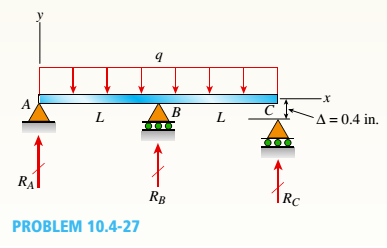
Chapter 10, Problem 10.4.27P
A beam rests on supports at A and B and is loaded by a distributed load with intensity q as shown. A small gap Δ exists between the unloaded beam and the support at C. Assume that span length L = 40 in. and flexural rigidity of the beam EI = 04 x 109lb-in2. Plot a graph of the bending moment at B as a function of the load intensity q.
Hint: See Example 9-9 for guidance on computing the deflection at C.
Expert Solution & Answer

Trending nowThis is a popular solution!

Students have asked these similar questions
Problem 1
Consider R has a functional relationship with variables in the form
R = K xq xx
using
show that
n
✓ - (OR 1.)
=
i=1
2
Их
Ux2
Ихэ
2
(177)² = ² (1)² + b² (12)² + c² (1)²
2
UR
R
x2
x3
4. Figure 3 shows a crank loaded by a force F = 1000 N and Mx = 40 Nm.
a. Draw a free-body diagram of arm 2 showing the values of all forces, moments, and
torques that act due to force F. Label the directions of the coordinate axes on this
diagram.
b. Draw a free-body diagram of arm 2 showing the values of all forces, moments, and
torques that act due to moment Mr. Label the directions of the coordinate axes on this
diagram.
Draw a free body diagram of the wall plane showing all the forces, torques, and
moments acting there.
d. Locate a stress element on the top surface of the shaft at A and calculate all the stress
components that act upon this element.
e. Determine the principal stresses and maximum shear stresses at this point at A.
3. Given a heat treated 6061 aluminum, solid, elliptical column with 200 mm length, 200 N
concentric load, and a safety factor of 1.2, design a suitable column if its boundary conditions
are fixed-free and the ratio of major to minor axis is 2.5:1. (Use AISC recommended values
and round the ellipse dimensions so that both axes are whole millimeters in the correct 2.5:1
ratio.)
Chapter 10 Solutions
Mechanics of Materials (MindTap Course List)
Ch. 10 - A propped cantilever steel beam is constructed...Ch. 10 - A fixed-end b earn is subjected to a point load at...Ch. 10 - A propped cantilever beam AB of a length L is...Ch. 10 - A fixed-end beam AB of a length L supports a...Ch. 10 - A cantilever beam AB of a length L has a fixed...Ch. 10 - A cantilever beam of a length L and loaded by a...Ch. 10 - A cantilever beam has a length L and is loaded by...Ch. 10 - A propped cantilever beam of a length L is loaded...Ch. 10 - A propped cantilever beam of a length L is loaded...Ch. 10 - A fixed-end beam of a length L is loaded by a...
Ch. 10 - A fixed-end b earn of a length L is loaded by a...Ch. 10 - A fixed-end beam of a length L is loaded by...Ch. 10 - A counterclockwise moment M0acts at the midpoint...Ch. 10 - A propped cantilever beam of a length L is loaded...Ch. 10 - A propped cantilever beam is subjected to uniform...Ch. 10 - Repeat Problem 10.3-15 using L = 3.5 m, max = 3...Ch. 10 - A two-span, continuous wood girder (E = 1700 ksi)...Ch. 10 - A fixed-end beam AB carries point load P acting at...Ch. 10 - A fixed-end beam AB supports a uniform load of...Ch. 10 - -4-4 A cantilever beam is supported at B by cable...Ch. 10 - A propped cantilever beam AB of a length L carries...Ch. 10 - A beam with a sliding support at B is loaded by a...Ch. 10 - A propped cantilever beam of a length 2L with a...Ch. 10 - The continuous frame ABC has a pin support at /l,...Ch. 10 - The continuous frame ABC has a pin support at A,...Ch. 10 - Beam AB has a pin support at A and a roller...Ch. 10 - The continuous frame ABCD has a pin support at B:...Ch. 10 - Two flat beams AB and CD, lying in horizontal...Ch. 10 - -4-13 A propped cantilever beam of a length 2L is...Ch. 10 - A propped cantilever beam of a length 2L is loaded...Ch. 10 - Determine the fixed-end moments (MAand MB) and...Ch. 10 - A continuous beam ABC wit h two unequal spans, one...Ch. 10 - Beam ABC is fixed at support A and rests (at point...Ch. 10 - A propped cantilever beam has flexural rigidity EI...Ch. 10 - A triangularly distributed 1oad with a maximum...Ch. 10 - A fixed-end beam is loaded by a uniform load q =...Ch. 10 - Uniform load q = 10 lb/ft acts over part of the...Ch. 10 - A propped cantilever beam with a length L = 4 m is...Ch. 10 - A cant i levé r b ea m i s supported by a tie rod...Ch. 10 - The figure shows a nonprismatic, propped...Ch. 10 - A beam ABC is fixed at end A and supported by beam...Ch. 10 - A three-span continuous beam A BCD with three...Ch. 10 - A beam rests on supports at A and B and is loaded...Ch. 10 - A propped cantilever beam is subjected to two...Ch. 10 - A propped cantilever beam is loaded by a...Ch. 10 - A fixed-end beam AB of a length L is subjected to...Ch. 10 - A temporary wood flume serving as a channel for...Ch. 10 - Two identical, simply supported beams AB and CD...Ch. 10 - The cantilever beam AB shown in the figure is an...Ch. 10 - The beam AB shown in the figure is simply...Ch. 10 - The continuous frame ABC has a fixed support at A,...Ch. 10 - The continuous frame ABC has a pinned support at...Ch. 10 - A wide-flange beam ABC rests on three identical...Ch. 10 - A fixed-end beam AB of a length L is subjected to...Ch. 10 - A beam supporting a uniform load of intensity q...Ch. 10 - A thin steel beam AB used in conjunction with an...Ch. 10 - Find an expression for required moment MA(in terms...Ch. 10 - Repeat Problem 10.4-41 for the loading shown in...Ch. 10 - A propped cantilever beam is loaded by two...Ch. 10 - A cable CD of a length H is attached to the third...Ch. 10 - A propped cantilever beam, fixed at the left-hand...Ch. 10 - Solve t he preceding problem by integrating the...Ch. 10 - A two-span beam with spans of lengths L and L/3 is...Ch. 10 - Solve the preceding problem by integrating the...Ch. 10 - Assume that the deflected shape of a beam AB with...Ch. 10 - (a) A simple beam AB with length L and height h...
Knowledge Booster


Learn more about
Need a deep-dive on the concept behind this application? Look no further. Learn more about this topic, mechanical-engineering and related others by exploring similar questions and additional content below.Similar questions
- 1. A simply supported shaft is shown in Figure 1 with w₁ = 25 N/cm and M = 20 N cm. Use singularity functions to determine the reactions at the supports. Assume El = 1000 kN cm². Wo M 0 10 20 30 40 50 60 70 80 90 100 110 cm Figure 1 - Problem 1arrow_forwardPlease AnswerSteam enters a nozzle at 400°C and 800 kPa with a velocity of 10 m/s and leaves at 375°C and 400 kPa while losing heat at a rate of 26.5 kW. For an inlet area of 800 cm2, determine the velocity and the volume flow rate of the steam at the nozzle exit. Use steam tables. The velocity of the steam at the nozzle exit is m/s. The volume flow rate of the steam at the nozzle exit is m3/s.arrow_forward2. A support hook was formed from a rectangular bar. Find the stresses at the inner and outer surfaces at sections just above and just below O-B. -210 mm 120 mm 160 mm 400 N B thickness 8 mm = Figure 2 - Problem 2arrow_forward
- Steam flows steadily through a turbine at a rate of 45,000 lbm/h, entering at 1000 psia and 900°F and leaving at 5 psia as saturated vapor. If the power generated by the turbine is 4.1 MW, determine the rate of heat loss from the steam. The enthalpies are h1 = 1448.6 Btu/lbm and h2 = 1130.7 Btu/lbm. The rate of heat loss from the steam is Btu/s.arrow_forwardThe A/D converter wit the specifications listed below is planned to be used in an environment in which the A/D converter temperature may change by ± 10 °C. Estimate the contributions of conversion and quantization errors to the uncertainty in the digital representation of an analog voltage by the converter. FSO N Linearity error Temperature drift error Analog to Digital (A/D) Converter 0-10 V 12 bits ± 3 bits 1 bit/5 °Carrow_forward6-13. A smooth tube in the form of a circle of radius r rotates in its vertical plane with a constant angular velocity w. The position of a particle of mass m that slides inside the tube is given by the relative coordinate p. Find the differential equation for . e О E g ω Figure P6-13arrow_forward
- Problem 2 Consider the power drawn by a resistance load in a DC circuit. The power is calculated as P = VI or P = 1²R. It is given that the normalized uncertainty or % percentage uncertainty in measurements of I, R, and V are the same. Find the uncertainty in P using the two different expressions for power. Is the uncertainty using the two methods the same? If not, WHY, explain?arrow_forwardA piston–cylinder device contains 3 kg of nitrogen initially at 100 kPa and 25°C. Nitrogen is now compressed slowly in a polytropic process during which PV1.3 = constant until the volume is reduced by one-half. Determine the work done and the heat transfer for this process. The gas constant of N2 is R = 0.2968 kPa·m3/kg·K. The cv value of N2 at the anticipated average temperature of 350 K is 0.744 kJ/kg·K (Table A-2b). The work done for this process is kJ. The heat transfer for this process is kJ.arrow_forwardI tried solving this one but I have no idea where I went wrong can you please help me out with this?arrow_forward
- During a picnic on a hot summer day, all the cold drinks disappear quickly, and the only available drinks are those at the ambient temperature of 85°F. In an effort to cool a 12- fluid-oz drink in a can, a person grabs the can and starts shaking it in the iced water of the chest at 32°F. Using the properties of water for the drink, determine the mass of ice that will melt by the time the canned drink cools to 37°F. The density and specific heat of water at the average temperature of (85+37)/2 = 61ºF are ρ = 62.3 lbm/ft3 and cp = 1.0 Btu/lbmºF (Table A-3E). The heat of fusion of water is 143.5 Btu/lbm. The mass of ice that will melt by the time the canned drink cools to 37°F is lbm.arrow_forwardSteam enters a nozzle at 400°C and 800 kPa with a velocity of 10 m/s and leaves at 375°C and 400 kPa while losing heat at a rate of 26.5 kW. For an inlet area of 800 cm2, determine the velocity and the volume flow rate of the steam at the nozzle exit. Use steam tables. At the left side of the lines, 800 kilo Pascal, 400 degree Centigrade, 10 meters per second are shown. At the right side of the lines, 400 kilo Pascal, 375 degree Centigrade are shown. The velocity of the steam at the nozzle exit is m/s. The volume flow rate of the steam at the nozzle exit is m3/s.arrow_forwardA saturated liquid–vapor mixture of water, called wet steam, in a steam line at 1450 kPa is throttled to 50 kPa and 100°C. What is the quality in the steam line? Use data from the steam tables. Above the right side of the tube, 50 kilos 100 degree Centigrade indicated. The quality in the steam line is .arrow_forward
arrow_back_ios
SEE MORE QUESTIONS
arrow_forward_ios
Recommended textbooks for you
 Mechanics of Materials (MindTap Course List)Mechanical EngineeringISBN:9781337093347Author:Barry J. Goodno, James M. GerePublisher:Cengage Learning
Mechanics of Materials (MindTap Course List)
Mechanical Engineering
ISBN:9781337093347
Author:Barry J. Goodno, James M. Gere
Publisher:Cengage Learning
Solids: Lesson 53 - Slope and Deflection of Beams Intro; Author: Jeff Hanson;https://www.youtube.com/watch?v=I7lTq68JRmY;License: Standard YouTube License, CC-BY