
Mechanics of Materials (MindTap Course List)
9th Edition
ISBN: 9781337093347
Author: Barry J. Goodno, James M. Gere
Publisher: Cengage Learning
expand_more
expand_more
format_list_bulleted
Videos
Textbook Question
Chapter 10, Problem 10.4.12P
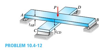
Two flat beams AB and CD, lying in horizontal planes, cross at right angles and jointly support a vertical load P at their midpoints (see figure). Before the load P is applied, the beams just touch each other. Both beams are made of the same material and have the same widths. Also, the ends of both beams are simply supported. The lengths of beams AB and CD are LABand LCD, respectively.
What should be the ratio tABltCDof the thicknesses of the beams if all four reactions arc to be the same?
Expert Solution & Answer

Trending nowThis is a popular solution!

Students have asked these similar questions
hi can use please answer question for attached
A uniform plank has length 6m and mam 40kg It is placed on horizontal ground at the edge of a vertical river bank, so that 1.5m of the plank is peojecting over the edge, as shown in Figure.27.
if you use * can you please tell me what u mean by it?
force, the sign convention is same as that used in lectures and seminars).
A simply supported beam is loaded as shown in the Figure. The corresponding SFD and BMD would be:
20 kN
10 kN/m
2 m
2 m
30 kN
(a)
40 kN m
30 kN
30 kN
10 kN
(b)
40 kN.m
10 kN
30 kN
30 kN
Click Save and Submit to save and submit. Click Save All Answers to save all answvers.
QUESTION 1
The beam in the figure below is made from three boards nailed together as shown. If the internal section width is 193 mm, find the location of the centrold of the cross section
relative to the botfom surface in mm (height to the centroid).
25 mm
150 mm
20 mm
w mm
M Nm
20 mm
Chapter 10 Solutions
Mechanics of Materials (MindTap Course List)
Ch. 10 - A propped cantilever steel beam is constructed...Ch. 10 - A fixed-end b earn is subjected to a point load at...Ch. 10 - A propped cantilever beam AB of a length L is...Ch. 10 - A fixed-end beam AB of a length L supports a...Ch. 10 - A cantilever beam AB of a length L has a fixed...Ch. 10 - A cantilever beam of a length L and loaded by a...Ch. 10 - A cantilever beam has a length L and is loaded by...Ch. 10 - A propped cantilever beam of a length L is loaded...Ch. 10 - A propped cantilever beam of a length L is loaded...Ch. 10 - A fixed-end beam of a length L is loaded by a...
Ch. 10 - A fixed-end b earn of a length L is loaded by a...Ch. 10 - A fixed-end beam of a length L is loaded by...Ch. 10 - A counterclockwise moment M0acts at the midpoint...Ch. 10 - A propped cantilever beam of a length L is loaded...Ch. 10 - A propped cantilever beam is subjected to uniform...Ch. 10 - Repeat Problem 10.3-15 using L = 3.5 m, max = 3...Ch. 10 - A two-span, continuous wood girder (E = 1700 ksi)...Ch. 10 - A fixed-end beam AB carries point load P acting at...Ch. 10 - A fixed-end beam AB supports a uniform load of...Ch. 10 - -4-4 A cantilever beam is supported at B by cable...Ch. 10 - A propped cantilever beam AB of a length L carries...Ch. 10 - A beam with a sliding support at B is loaded by a...Ch. 10 - A propped cantilever beam of a length 2L with a...Ch. 10 - The continuous frame ABC has a pin support at /l,...Ch. 10 - The continuous frame ABC has a pin support at A,...Ch. 10 - Beam AB has a pin support at A and a roller...Ch. 10 - The continuous frame ABCD has a pin support at B:...Ch. 10 - Two flat beams AB and CD, lying in horizontal...Ch. 10 - -4-13 A propped cantilever beam of a length 2L is...Ch. 10 - A propped cantilever beam of a length 2L is loaded...Ch. 10 - Determine the fixed-end moments (MAand MB) and...Ch. 10 - A continuous beam ABC wit h two unequal spans, one...Ch. 10 - Beam ABC is fixed at support A and rests (at point...Ch. 10 - A propped cantilever beam has flexural rigidity EI...Ch. 10 - A triangularly distributed 1oad with a maximum...Ch. 10 - A fixed-end beam is loaded by a uniform load q =...Ch. 10 - Uniform load q = 10 lb/ft acts over part of the...Ch. 10 - A propped cantilever beam with a length L = 4 m is...Ch. 10 - A cant i levé r b ea m i s supported by a tie rod...Ch. 10 - The figure shows a nonprismatic, propped...Ch. 10 - A beam ABC is fixed at end A and supported by beam...Ch. 10 - A three-span continuous beam A BCD with three...Ch. 10 - A beam rests on supports at A and B and is loaded...Ch. 10 - A propped cantilever beam is subjected to two...Ch. 10 - A propped cantilever beam is loaded by a...Ch. 10 - A fixed-end beam AB of a length L is subjected to...Ch. 10 - A temporary wood flume serving as a channel for...Ch. 10 - Two identical, simply supported beams AB and CD...Ch. 10 - The cantilever beam AB shown in the figure is an...Ch. 10 - The beam AB shown in the figure is simply...Ch. 10 - The continuous frame ABC has a fixed support at A,...Ch. 10 - The continuous frame ABC has a pinned support at...Ch. 10 - A wide-flange beam ABC rests on three identical...Ch. 10 - A fixed-end beam AB of a length L is subjected to...Ch. 10 - A beam supporting a uniform load of intensity q...Ch. 10 - A thin steel beam AB used in conjunction with an...Ch. 10 - Find an expression for required moment MA(in terms...Ch. 10 - Repeat Problem 10.4-41 for the loading shown in...Ch. 10 - A propped cantilever beam is loaded by two...Ch. 10 - A cable CD of a length H is attached to the third...Ch. 10 - A propped cantilever beam, fixed at the left-hand...Ch. 10 - Solve t he preceding problem by integrating the...Ch. 10 - A two-span beam with spans of lengths L and L/3 is...Ch. 10 - Solve the preceding problem by integrating the...Ch. 10 - Assume that the deflected shape of a beam AB with...Ch. 10 - (a) A simple beam AB with length L and height h...
Knowledge Booster


Learn more about
Need a deep-dive on the concept behind this application? Look no further. Learn more about this topic, mechanical-engineering and related others by exploring similar questions and additional content below.Similar questions
- Consider the beam in the picture below: 7kN/m 5kN/m P N/m Section 1 Section 2 Section 3 - L/3 L/3 L/3 %3D Take P = the last four digits of your student number in N/m. If P<250 N/m then take P = 30OON/m instead. Take L = the third digit of your student number, reading left to reight. If this value is zero then take L = 2 Assume: The reaction at the Pin = V pin 47000L+9PL )N 54 The reaction at the Roller = Vroller = 61000L+9PL 54 and that both reactions act vertically upwards. a) Find an expression for the internal moment for Section 1. Show all working and any relevant free body diagrams. b) What is the maximum magnitude of the internal moment for Section 1? Mark sure you prove that the value you calculate is the maximum. c) Find an expression for the internal moment for Section 2. Show all working and any relevant free body diagrams. d) What is the maximum magnitude of the internal moment for Section 2? Mark sure you prove that the value you calculate is the maximum. e) Find an…arrow_forwardThis question is made of two separate parts related to figures 1 and 2. 3 m a Figure 1 2 m in in B direction A| direction L Figure 1 A beam AB is supported by a pin at A and a roller at B. The beam is subjected to force F of 450N, making an angle a-400 with horizontal as shown in figure 1. The support reaction at pin A along x-axis is to the The support reaction at pin A along y-axis is The support reaction at roller B is Figure 2 B 4 Figure 2 A beam AB of length L-1 m is supported by a pin at A and a cable BC at point B. The beam is subject to an external moment M-550 N.m at B as shown in figure 2. The force in cable BC is and it is in 3 с.arrow_forwardFigure below shows a beam acted upon a triangular distributed load. What is the magnitude and location of the equivalent concentrated load? 5 kN/m 4 m 4 m 5kN, 4m from the left 10KN, 2m from the left 10KN, 1.33 m from the left 20KN, 6.67 m from the rightarrow_forward
- Consider the beam cross-section and the direction of moment (shown in side view) applied as shown in Figure Q2. All dimensions are in mm. Note the square hole in the cross-section. (a) Locate the neutral axis of the beam cross-section (y-coordinate from the bottom of the section). Please draw a larger schematic and neatly label all distances for calculating the neutral axis. (b) What is the area moment of inertia of the cross-section with respect to the neutral axis? (c) If the applied bending moment M=5kN.m, then determine the maximum bending stress (absolute value, tensile or compressive) anywhere on the beam.arrow_forwardA water gate is to be reinforced with three horizontal beams (running to the page). If the water acts on one side only to a depth of h=6m, find the positions of the beams measured from the water surface so that each beam will carry an equal load. Gate is fully covered by water. [²] = 24 R =arrow_forwardThis question is made of two separate parts related to figures 1 and 2. 2 m F Figure 1 2 m in A direction L direction Figure 2 Figure 1 D A beam AB is supported by a pin at A and a roller at B. The beam is subjected to force F of 5 KN, making an angle a=400 with horizontal as shown in figure 1. The support reaction at pin A along x-axis is to the The support reaction at pin A along y-axis is The support reaction at roller B is M B Figure 2 A beams AB of length L-2 m is supported by a pin at A and a cable BC at point B. The beam is subject to an external moment M=200 N.m at B as shown in figure 2. The force in cable BC is and it is inarrow_forward
- The bending moment Mx affects the cross section of the beam given in Figure 4. Beam cross section Calculation of normal stress at points 1,2,3 and normal Plot the stress distribution. a (mm)=255 b (mm)=40 c (mm)=230 d (mm)=50 Mx (kNm)= 53arrow_forwardA cross-section of a beam is shown in Figure Q2. If the shear force in this section is V 163 KN, determine the value and the location of the maximum shear stress in the section. In Figure Q2, a = 77 mm and the origin of the coordinate system is at centroid of the cross section. y= A Z= a mm; 2a mm; O 4a The vertical coordinate (y-coordinate; the y-axis serves as the axis of symmetry of the cross-section.) and horizontal coordinate (z-coordinate) of the location where the maximum shear stress occurs in the section are Figure Q2 3a a The vertical distance from the location where the maximum shear stress occurs in the section to the bottom side (AB) of the cross section can be calculated as Distance = mmarrow_forwardA uniform beam is fixed at end x=0 and simply supported at x = L. Find the shape of the center line of the beam, given the weight per unit Length is w. a. b. C. e. O y(x) = d. y(x) = a y(x) = y(x) = y(x) = W 24 El -[x4 - 4Lx³ +6L²x²] =[x4-2Lx³ + L²x²] -[x4-2Lx³ + L³x] -[2x4-5Lx³+3L²x²] [2x4-3L³x³ +3L²x²] W 24 El W 24 El W 24 El - W 24 EIarrow_forward
- Draw the complete shearing force and bending moment diagram for the beam shown in figure (2). Use the last TWO digit of your ID Number for the missing force (F). 75 4 m F KN/m 4 m 12 m Figure (2)arrow_forwardBeam ABC in the figure is loaded as shown. Determine the support reactions. 80KN 20KN/m -30kN 60KN-m [2m BA -am-t-am- 3ma 2m' 2marrow_forward1. Three cubes of side l0, 2l0, and 3l0, are placed next to another (in contact) with their centers along a straight line and the l = 2l0 cube is in the middle (see Figure below).a) If the cubes are made of the same uniform material, find along this line the position of the center of mass of the system.b) We now replace the cube in the middle (l = 2l0) by another cube of the same volume but made of a different uniform material. What would be the mass density of this cube compared to the mass density 0 of the initial cube if we want to locate the center of mass of the new system at the interface between the cube in the middle (l = 2l0) and the right-hand cube (l = 3l0)?arrow_forward
arrow_back_ios
SEE MORE QUESTIONS
arrow_forward_ios
Recommended textbooks for you
 Elements Of ElectromagneticsMechanical EngineeringISBN:9780190698614Author:Sadiku, Matthew N. O.Publisher:Oxford University Press
 Mechanics of Materials (10th Edition)Mechanical EngineeringISBN:9780134319650Author:Russell C. HibbelerPublisher:PEARSON
 Thermodynamics: An Engineering ApproachMechanical EngineeringISBN:9781259822674Author:Yunus A. Cengel Dr., Michael A. BolesPublisher:McGraw-Hill Education
 Control Systems EngineeringMechanical EngineeringISBN:9781118170519Author:Norman S. NisePublisher:WILEY
 Mechanics of Materials (MindTap Course List)Mechanical EngineeringISBN:9781337093347Author:Barry J. Goodno, James M. GerePublisher:Cengage Learning
 Engineering Mechanics: StaticsMechanical EngineeringISBN:9781118807330Author:James L. Meriam, L. G. Kraige, J. N. BoltonPublisher:WILEY
Elements Of Electromagnetics
Mechanical Engineering
ISBN:9780190698614
Author:Sadiku, Matthew N. O.
Publisher:Oxford University Press
Mechanics of Materials (10th Edition)
Mechanical Engineering
ISBN:9780134319650
Author:Russell C. Hibbeler
Publisher:PEARSON
Thermodynamics: An Engineering Approach
Mechanical Engineering
ISBN:9781259822674
Author:Yunus A. Cengel Dr., Michael A. Boles
Publisher:McGraw-Hill Education
Control Systems Engineering
Mechanical Engineering
ISBN:9781118170519
Author:Norman S. Nise
Publisher:WILEY
Mechanics of Materials (MindTap Course List)
Mechanical Engineering
ISBN:9781337093347
Author:Barry J. Goodno, James M. Gere
Publisher:Cengage Learning
Engineering Mechanics: Statics
Mechanical Engineering
ISBN:9781118807330
Author:James L. Meriam, L. G. Kraige, J. N. Bolton
Publisher:WILEY
Mechanics of Materials Lecture: Beam Design; Author: UWMC Engineering;https://www.youtube.com/watch?v=-wVs5pvQPm4;License: Standard Youtube License