
Videos
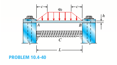
A thin steel beam AB used in conjunction with an electromagnet in a high-energy physics experiment is securely bolted to rigid supports (see figure), A magnetic field produced by coils C results in a force acting on the beam. The force is trapezoidally distributed with maximum intensity q0= 18 kN/m. The length of the beam between supports is L = 200 mm, and the dimension c of the trapezoidal load is 50 mm. The beam has a rectangular cross section with width b = 60 and height h = 20 mm.
Determine the maximum bending stress
The maximum bending stress and the maximum deflection.
Answer to Problem 10.4.40P
The maximum bending stress is
The maximum deflection in the beam is
Explanation of Solution
Given information:
Width of the rectangular cross-section is
The below figure shows the schematic diagram of the beam with parameters.
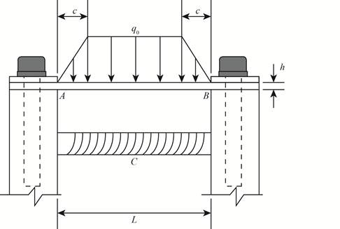
Figure-(1)
Write the expression for the equilibrium in vertical direction.
Substitute
Here, the reaction force at point A is
There is symmetry in the beam therefore the reaction forces at A and B will be same.
There is symmetry in the beam therefore the moment at A will be equal to moment at B .
Write the expression for the relation between the reaction forces at A and B .
Write the expression for the relation between the moment about A and B .
Here, the moment about A is
The below figure shows the deflection in the beam.
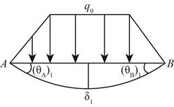
Figure-(2)
Write the expression for the compatibility.
Here, the rotation about point A is
The below figure shows the deflection slope.
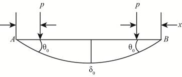
Figure-(3)
Write the expression for the slope from figure-(3).
Here, the load is
Write the expression for the deflection for figure-(3).
Write the expression for load.
Write the expression for load from
Write the expression for load from
Write the expression for rotation about A .
Write the expression for the deflection.
The below figure shows the moments at the ends of the beam.
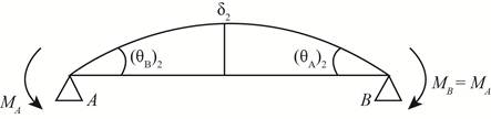
Figure-(4)
Write the expression for the compatibility.
Write the expression for slope for figure-(4).
Write the expression for the deflection for figure-(4).
Write the expression for maximum deflection.
Substitute
Write the expression for the moment about C .
Write the expression for the maximum moment.
Write the expression for moment of inertia.
Here, moment of inertia is
Write the expression for the section modulus.
Write the expression for the normal stress.
Calculation:
Substitute
Substitute
Substitute
Substitute
Substitute
Substitute
Substitute
Substitute
Substitute
Conclusion:
The maximum bending stress is
The maximum deflection in the beam is
Want to see more full solutions like this?
Chapter 10 Solutions
Mechanics of Materials (MindTap Course List)


- A column ABC is supported at ends A and C and compressed by an axial load P (figure a). Lateral support is provided at point B but only in the plane of the figure; lateral support perpendicular to the plane of the figure is provided only at A and C. The column is constructed of two channel sections (C 6 × 8.2) back to back (see figure b). The modulus of elasticity of the column is E = 29,500 ksi and the proportional limit is 50 ksi. The height of the column is L = 15 ft. Find the allowable value of load P using a factor of safety of 2.5.arrow_forwardAn aluminum wire having a diameter d = 1/10 in. and length L = 12 ft is subjected to a tensile load P (see figure). The aluminum has a modulus of elasticity E = 10,600 ksi If the maximum permissible elongation of the wire is l/8 in. and the allowable stress in tension is 10 ksi, what is the allowable load Pmax?arrow_forwardA prismatic bar AD of length L, cross-sectional area A. and modulus of elasticity E is subjected to loads 5P, 3P, and P acting at points B, C, and D, respectively (see figure). Segments AB, BC, and CD have lengths L/6, L/2, and L/3, respectively. (a) Obtain a formula for the strain energy U of the bar. (b) Calculate the strain energy if P = 6 kips, L = 52 in., A = 2.76 in2, and the material is aluminum with E = 10.4 × 10⁶ psi.arrow_forward
- A vertical pole of solid, circular cross section is twisted by horizontal forces P = 5kN acting at the ends of a rigid horizontal arm AB (see figure part a). The distance from the outside of the pole to the line of action of each force is c = 125 mm (sec figure part b) and the pole height L = 350 mm. (a) If the allowable shear stress in the pole is 30 MPa, what is the minimum required diameter dminof the pole? (b) What is the torsional stiffness of the pole (kN · m/rad)? Assume that G = 28 GPa. (c) If two translation al springs, each with stiffness k =2550 kN/m, are added at 2c/5 from A and B (see figure part c), repeat part (a) to find dmin. Hint: Consider the pole and pair of springs as "springs in parallel."arrow_forwardA weight W = 4500 lb falls from a height h onto a vertical wood pole having length L = 15 ft, diameter d = 12 in., and modulus of elasticity E = 1.6 × 10⁶ psi (see figure). If the allowable stress in the wood under an impact load is 2500 psi. what is the maximum permissible height h?arrow_forwardBeam ABCD represents a reinforced-concrete foundation beam that supports a uniform load of intensity q1= 3500 lb/ft (see figure). Assume that the soil pressure on the underside of the beam is uniformly distributed with intensity q2 Find the shear force VBand bending moment MBat point B. Find the shear force Vmand bending moment M at the midpoint of the beam.arrow_forward
- A round bar ABC of length 2L (see figure) rotates about an axis through the midpoint C with constant angular speed w (radians per second). The material of the bar has weight density y. (a) Derive a formula for the tensile stress a’ in the bar as a function of the distance x from the midpoint C. (b) What is the maximum tensile stress a max?arrow_forwardA beam is constructed using two angle sections (L 102 × 76 × 6.4) arranged back to back, as shown in the figure. The beam is fixed al joint A and attached to an elastic support having a spring constant k = l750 kN/m al joint B. Assume only the beam is subjected to temperature increase AT = 45°C. Calculate the thermal stress developed in the beam and the displacement at point B. Assume that a = 12 X 10-6/?. Let E = 205 GPaarrow_forwardSegments A B and BCD of beam A BCD are pin connected at x = 4 m. The beam is supported by a sliding support at A and roller supports at C and D (see figure). A triangularly distributed load with peak intensity of SO N/m acts on EC. A concentrated moment is applied at joint D. (a) Find reactions at supports A, C, and D. (b) Find internal stress resultants N, Y, and Mat x = 5m. (c) Repeat parts (a) and (b) for die case of the roller support at C replaced by a linear spring of stiffness kr™ 200 kN/m (see figure).arrow_forward
- A vertical pole of solid, circular cross section is twisted by horizontal forces P = 1100 lb acting at the ends of a rigid horizontal arm AB (see figure part a). The distance from the outside of the pole to the line of action of each force is c = 5.0 in. (see figure part b) and the pole height is L = 14in. (a) If the allowable shear stress in the pole is 4500 psi, what is the minimum required diameter dminof the pole? Find the torsional stiffness of the pole (kip-in./rad). Assume that G = 10,800 ksi. If two translational springs, each with stiffness k = 33 kips/in., are added at 2(75 from A and B (see figure part c), repeat part (a) to find dmin. Hint: Consider the pole and pair of springs as "springs in parallel."arrow_forwardTwo pipe columns (AB, FC) are pin-connected to a rigid beam (BCD), as shown in the figure. Each pipe column has a modulus of E, but heights (L1or L2) and outer diameters (d1or different for each column. Assume the inner diameter of each column is 3/4 of outer diameter. Uniformly distributed downward load q = 2PIL is applied over a distance of 3L/4 along BC, and concentrated load PIA is applied downward at D. (a) Derive a formula for the displacementarrow_forwardA rigid bar ACB is supported on a fulcrum at C and loaded by a Force P at end B (see figure). Three identical wires made of an elasloplastic material (yield stress oYand modulus of elasticity E) resist tbe load P. Each wire has cross-sectional area A and length L. (a) Determine the yield load PYand the corresponding yield displacement Syat point B. (b) Determine the plastic load PPand the corresponding displacementarrow_forward
 Mechanics of Materials (MindTap Course List)Mechanical EngineeringISBN:9781337093347Author:Barry J. Goodno, James M. GerePublisher:Cengage Learning