
Fundamentals of Electromagnetics with Engineering Applications
1st Edition
ISBN: 9780470105757
Author: Stuart M. Wentworth
Publisher: Wiley, John & Sons, Incorporated
expand_more
expand_more
format_list_bulleted
Concept explainers
Videos
Textbook Question
Chapter 10, Problem 10.12P
Find the scattering matrices for the simple two-port networks shown in Figure 10.50.
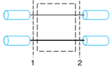
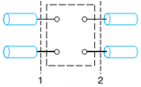
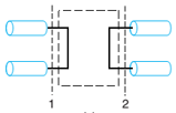
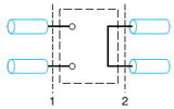
Figure 10.50 Two-port networks for finding [S] in Problem 10.12.
Expert Solution & Answer
Want to see the full answer?
Check out a sample textbook solution
Students have asked these similar questions
What is the impact on the demodulated constellation diagram? What effect does it have on the image before demodulation? What is the reason? (Hint: related to channel gain)
(a) Explain on the AM Single Sideband Full Carrier (SSBFC) and compare to DoubleSide Band Full Carrier (DSBFC) on their:(iv) Carrier power.(v) Sideband power
For an FM modulator with modulation index m (as in table
modulating signal v„(t) = cos(2nf„t) (Fm as in table Q1), and
an unmodulated carrier
v.(t) = 10 cos (2nf t) (f_as in table Q1) Assume R,=502
i) Determine the number of sets of significant sidebands.
ii)
Determine
their
amplitudes.
iii) Draw the frequency spectrum showing the relative
amplitudes
of
the
side
frequencies.
iv) Determine the bandwidth.
v) Determine the total power of the modulated wave.
Table Q1
Student Name Index mf(Hz)\f. (kHz)
LAKSHMI
1.5
1200 1000
LJINA
1400 800
MAZOUN
0.5
1600 600
|МОНАММED
1800 700
Chapter 10 Solutions
Fundamentals of Electromagnetics with Engineering Applications
Ch. 10 - A matching network consists of a length of a...Ch. 10 - Design an L-section matching network to match a...Ch. 10 - Design an L-section matching network to match an...Ch. 10 - Design an L-section matching network to match a...Ch. 10 - Suppose you want to match a 100 line to a load...Ch. 10 - Prob. 10.7PCh. 10 - Prob. 10.8PCh. 10 - Prob. 10.9PCh. 10 - Prob. 10.10PCh. 10 - Suppose the L-section matching network of Example...
Ch. 10 - Find the scattering matrices for the simple...Ch. 10 - Cut a 50- T-line and insert a series 50- resistor...Ch. 10 - Prob. 10.14PCh. 10 - A series capacitor of value C=2.0pF is inserted in...Ch. 10 - A series inductor of value L=3.5nH is inserted in...Ch. 10 - Prob. 10.17PCh. 10 - The scattering matrix (assuming a 50- impedance...Ch. 10 - Three T-lines with the same characteristic...Ch. 10 - Consider a three-port network that is matched at...Ch. 10 - Prob. 10.21PCh. 10 - Calculate the insertion loss and the VSWR for the...Ch. 10 - Prob. 10.23PCh. 10 - Verify the scattering matrix (10.27) for the...Ch. 10 - Prob. 10.25PCh. 10 - Prob. 10.26PCh. 10 - A four-port 20-dB coupler is specified as having...Ch. 10 - Suppose the coupling for an ideal symmetrical...Ch. 10 - Suppose to port 1 of an ideal ring hybrid coupler...Ch. 10 - Prob. 10.30PCh. 10 - Prob. 10.31PCh. 10 - Prob. 10.32PCh. 10 - Suppose you join a pair of quadrature hybrid...Ch. 10 - Prob. 10.34PCh. 10 - Prob. 10.35PCh. 10 - Prob. 10.36PCh. 10 - Prob. 10.37PCh. 10 - Prob. 10.38PCh. 10 - Prob. 10.39PCh. 10 - Prob. 10.40PCh. 10 - Starting with the Figure 10.28b circuit...Ch. 10 - Starting with the Figure lO.28b circuit...Ch. 10 - Prob. 10.43PCh. 10 - Starting with the Figure 10.28a circuit...Ch. 10 - Prob. 10.45PCh. 10 - For Problem 10.45, (a) design open-ended shunt...Ch. 10 - Prob. 10.47PCh. 10 - Prob. 10.48PCh. 10 - Prob. 10.49PCh. 10 - Prob. 10.50PCh. 10 - Prob. 10.51PCh. 10 - Referring to Example 10.21 and Figure 10.48,...
Knowledge Booster


Learn more about
Need a deep-dive on the concept behind this application? Look no further. Learn more about this topic, electrical-engineering and related others by exploring similar questions and additional content below.Similar questions
- 10. For a single-conversion SSB transmitter, an audio frequency is ranging from 0 to 4 kHz, and HF carrier frequency is 27 MHz, Sketch the output frequency spectrum. Also, if there is a single-frequency input signal of 1.8 kHz, determine the output frequency.arrow_forwardlator by any required amount. the carries frequency f. and the deviation Example 10.4 A direct-FM transmitter has a varactor modulator with kf = 2 kHz/V and a maximum deviation of 300 Hz. This modulator is followed by a buffer and three stages of frequency multiplication: a tripler, a doubler, and another tripler, followed by a driver and power amplifier. 1) Draw a block diagram of this transmitter. 2) Will this transmitter be capable of 5 kHz deviation at the output? 3) What should the oscillator frequency be if the transmitter is to operate at a carrier frequency of 150 MHz? 4) What audio voltage will be required at the modulator input to obtain full deviation?arrow_forwardWhat happens with coupling capacitance in high frequency response using voltage divider configuration? Your answer What happens with coupling capacitance in low frequency response using bypassed emitter bias configuration? Your answer What is the value of the miller's output capacitance(FET) if Av is greater than 10? Your answer If the second critical frequency was reached, what is the roll off? Your answerarrow_forward
- 6-1. You are designing an FDM-PCM/FDMA analog link that will occupy 36 MHz of an INTELSAT VI transponder with 10 users of equal bandwidth. The uplink and downlink center frequencies of the occupied band are 5985.5 MHz and 3760.5 MHz. The distance from the satellite to your earth station is 40,000 km. The saturation uplink flux density (total - all carriers) for your uplink is - 75 dBW/m2 and the satellite's G/T is = -11.6 dB/K. At saturation, the transponder EIRP for your downlink is 29 dBW and the earth station's G/T is 41 dB/K. Assume that the transponder is linear (an unrealistic scenario - but do it this way such that BOI = BOo, dB. The intermodulation carrier to noise ratio, (C/N), in dB, is related to the back-off BOo in dB by (C/N)31M = 7.86 - 0.714 * BO0 In other words, at Xponder saturation the value of (C/N)31M = 7.86 dB and for example BOo = -6 dB the (C/N)31M = 7.86 0.714*(-6) = 12.14 dB. (a) Find the maximum overall carrier-to-noise ratio (C/N), in dB that this link can…arrow_forwardIf the carrier signal is given as c(t)=5cos10000t, and the modulating signal is given as m (t) = 4e2rtthen the power (in watt) of the modulated DSB-SC signal is:arrow_forwardHow could I get the thevnin voltage from this using the transfer funciton and the lookback method?arrow_forward
- What are the Advantages and Disadvantages (Regarding to complexity of implementation, ease of demodulation , AM receiver expensivity and inexpensivity, power efficiency and noise) Of:- 1-Double sideband large (Full) carrier. 2-Double sideband suppressed carrier. 3-Single sideband suppressed carrier. 4-Vestigial sideband suppressed carrier. 2:57 PM Varrow_forwardFor an FM modulator with a modulation index mf = 1, a modulating signalVm(t) = Vm sin(2π1000t) and unmodulated carrier Vc(t) = 10 sin(2π500kt),determinea) Number of sets of significant sidebandb) Their amplitudec) Then draw the frequency spectrum showing their relative amplitudesd) Determine the unmodulated carrier power for the FM modulator(assume a load resistance RL = 50 Ω)e) Determine the power in the modulated carrier and each side frequency,and sketch the power spectrum for the modulated wave.arrow_forward24. The power of DSSS systems is largely in the spreading and dispreading of the received signal because it gives rise to a phenomenon known as ______________.A. channel codingB. spectral regrowthC. processing gain5D. frequency-hoppingarrow_forward
- 1- Explain the principle of direct method generation of FM signal.2- What is the difference between narrowband FM and wideband FM refer tothe spectral component of the two signals.3- Compare the S/N ratio of:a) AM DSB-LCb) AM SSB-SCc) FM4- Explain the operation of frequency demodulation by using the PLL method.5- Explain what Carson's rule is.arrow_forwardCGD CGS VDD ERD M₁ M : Сов Zin For this common-source stage, the parasitic capacitances in M₁ are: CGs=0.8pF, CGD=0.2pF, CDB=0.01pF. Let gm of M₁=1mA/V, RD=5kohm, ignore channel lenght modulation effect. The absolute vaule of Zin at 10Mrad/sec = Mrad/sec. HI HH" HH" kohm; while the pole of the output terminal (at drain of M1)=arrow_forwardIf the channel is AWGN channel with noise power spectral density of NO/2, then the probability of error using union bound at the output of the MLD receiver is equal to or less than * Q (0.25/ /2N.) Q (0.125/ /2N.) none of these Q (0.35/ /2N,)arrow_forward
arrow_back_ios
SEE MORE QUESTIONS
arrow_forward_ios
Recommended textbooks for you
 Introductory Circuit Analysis (13th Edition)Electrical EngineeringISBN:9780133923605Author:Robert L. BoylestadPublisher:PEARSON
 Delmar's Standard Textbook Of ElectricityElectrical EngineeringISBN:9781337900348Author:Stephen L. HermanPublisher:Cengage Learning
 Programmable Logic ControllersElectrical EngineeringISBN:9780073373843Author:Frank D. PetruzellaPublisher:McGraw-Hill Education
 Fundamentals of Electric CircuitsElectrical EngineeringISBN:9780078028229Author:Charles K Alexander, Matthew SadikuPublisher:McGraw-Hill Education
 Electric Circuits. (11th Edition)Electrical EngineeringISBN:9780134746968Author:James W. Nilsson, Susan RiedelPublisher:PEARSON
 Engineering ElectromagneticsElectrical EngineeringISBN:9780078028151Author:Hayt, William H. (william Hart), Jr, BUCK, John A.Publisher:Mcgraw-hill Education,
Introductory Circuit Analysis (13th Edition)
Electrical Engineering
ISBN:9780133923605
Author:Robert L. Boylestad
Publisher:PEARSON
Delmar's Standard Textbook Of Electricity
Electrical Engineering
ISBN:9781337900348
Author:Stephen L. Herman
Publisher:Cengage Learning
Programmable Logic Controllers
Electrical Engineering
ISBN:9780073373843
Author:Frank D. Petruzella
Publisher:McGraw-Hill Education
Fundamentals of Electric Circuits
Electrical Engineering
ISBN:9780078028229
Author:Charles K Alexander, Matthew Sadiku
Publisher:McGraw-Hill Education
Electric Circuits. (11th Edition)
Electrical Engineering
ISBN:9780134746968
Author:James W. Nilsson, Susan Riedel
Publisher:PEARSON
Engineering Electromagnetics
Electrical Engineering
ISBN:9780078028151
Author:Hayt, William H. (william Hart), Jr, BUCK, John A.
Publisher:Mcgraw-hill Education,
What is the Difference Between Single Phase and Three Phase???; Author: Electrician U;https://www.youtube.com/watch?v=FEydcr4wJw0;License: Standard Youtube License