
Fundamentals of Electromagnetics with Engineering Applications
1st Edition
ISBN: 9780470105757
Author: Stuart M. Wentworth
Publisher: Wiley, John & Sons, Incorporated
expand_more
expand_more
format_list_bulleted
Concept explainers
Videos
Textbook Question
Chapter 10, Problem 10.19P
Three T-lines with the same characteristic impedance Zo are connected as shown in Figure 10.51. (a) Determine the scattering matrix that represents this three-port network. (b) Is this network reciprocal? (c) Is it lossless?
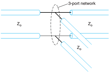
Figure 10.51 Finding [S] for the three-port network for Problem 10.19.
Expert Solution & Answer
Want to see the full answer?
Check out a sample textbook solution
Students have asked these similar questions
A signal with a power level of 4 mW is applied to the input of a directional coupler. The output from the main guide is measured at 2.2 dBm and the output from the secondary guide is measured at -18 dBm.
A.) Calculate the insertion loss for this device in dBs.
B.) Calculate the coupling loss for this device in dBs.
Is the small signal model of the circuit correct?If yes, proceed in answering the questions; if not, correct the model first, then answer the questions. Note: ignore the parasitic capacitances
What are the Advantages and Disadvantages
(Regarding to complexity of implementation, ease of demodulation , AM receiver
expensivity and inexpensivity, power efficiency and noise)
Of:-
1-Double sideband large (Full) carrier.
2-Double sideband suppressed carrier.
3-Single sideband suppressed carrier.
4-Vestigial sideband suppressed carrier.
2:57 PM V
Chapter 10 Solutions
Fundamentals of Electromagnetics with Engineering Applications
Ch. 10 - A matching network consists of a length of a...Ch. 10 - Design an L-section matching network to match a...Ch. 10 - Design an L-section matching network to match an...Ch. 10 - Design an L-section matching network to match a...Ch. 10 - Suppose you want to match a 100 line to a load...Ch. 10 - Prob. 10.7PCh. 10 - Prob. 10.8PCh. 10 - Prob. 10.9PCh. 10 - Prob. 10.10PCh. 10 - Suppose the L-section matching network of Example...
Ch. 10 - Find the scattering matrices for the simple...Ch. 10 - Cut a 50- T-line and insert a series 50- resistor...Ch. 10 - Prob. 10.14PCh. 10 - A series capacitor of value C=2.0pF is inserted in...Ch. 10 - A series inductor of value L=3.5nH is inserted in...Ch. 10 - Prob. 10.17PCh. 10 - The scattering matrix (assuming a 50- impedance...Ch. 10 - Three T-lines with the same characteristic...Ch. 10 - Consider a three-port network that is matched at...Ch. 10 - Prob. 10.21PCh. 10 - Calculate the insertion loss and the VSWR for the...Ch. 10 - Prob. 10.23PCh. 10 - Verify the scattering matrix (10.27) for the...Ch. 10 - Prob. 10.25PCh. 10 - Prob. 10.26PCh. 10 - A four-port 20-dB coupler is specified as having...Ch. 10 - Suppose the coupling for an ideal symmetrical...Ch. 10 - Suppose to port 1 of an ideal ring hybrid coupler...Ch. 10 - Prob. 10.30PCh. 10 - Prob. 10.31PCh. 10 - Prob. 10.32PCh. 10 - Suppose you join a pair of quadrature hybrid...Ch. 10 - Prob. 10.34PCh. 10 - Prob. 10.35PCh. 10 - Prob. 10.36PCh. 10 - Prob. 10.37PCh. 10 - Prob. 10.38PCh. 10 - Prob. 10.39PCh. 10 - Prob. 10.40PCh. 10 - Starting with the Figure 10.28b circuit...Ch. 10 - Starting with the Figure lO.28b circuit...Ch. 10 - Prob. 10.43PCh. 10 - Starting with the Figure 10.28a circuit...Ch. 10 - Prob. 10.45PCh. 10 - For Problem 10.45, (a) design open-ended shunt...Ch. 10 - Prob. 10.47PCh. 10 - Prob. 10.48PCh. 10 - Prob. 10.49PCh. 10 - Prob. 10.50PCh. 10 - Prob. 10.51PCh. 10 - Referring to Example 10.21 and Figure 10.48,...
Knowledge Booster


Learn more about
Need a deep-dive on the concept behind this application? Look no further. Learn more about this topic, electrical-engineering and related others by exploring similar questions and additional content below.Similar questions
- a.) Unmodulated carrier power. b.) Total sideband power.arrow_forwardA 50-ohm source has an RMS open-circuit output voltage of 1 volt at 100 MHz a. What peak voltage will appear across a 50-ohm load connected to this source b. Express this voltage in dBm. (Hint: careful of peak/rms voltage.) c. If the source is connected to the 50-ohm load through a lossless 50-ohm cable, what will the peak voltage at the load be? e. d. If the source is connected through a 50-ohm load through a 100-ft lossy 50-ohm cable, and the loss is 0.5 dB/10 ft, what will be the peak voltage at the load? Say that the "peak" (not RMS) voltage in part a. was 1 volt (i.e. the sinusoidal signal ranged from -1 to +1 volts). What would be the reading across a 50-ohm load in this case, if measured by a spectrum analyzer? Note that a spectrum analyzer produces a reading in dBm, not volts. Assume are no cables in this case. Indicato which of the foll 150arrow_forwardProblem 2 AConsider a cellular system of hexagonal structure. It is assumed that all the base stations transmit with the same power and the path loss follow the break-point model with exponent 4. The required S/I (signal power to interference power ratio) is 12dB. The fading margin is 10dB. What is the minimum cluster size?arrow_forward
- Q2: Define the Demodulation and compare between the coherent and Non-coherent detection. Q3: A carrier wave of frequency 2.5 GHz amplitude is modulated with two modulating frequencies equal to 1KHZ and 2KHZ. find the total bandwidth of the modulated wave. Q4: A Sinusoidal carrier frequency of 1.2MHZ is amplitude modulated by a sinusoidal voltage of frequency 20KHz resulting in maximum and minimum modulated carrier amplitude of 110V & 90V respectively. Calculate: I. frequency of lower and upper side bands. II. unmodulated carrier amplitude. III. Modulation index. IV. Amplitude of each side band.arrow_forwardQ5) In a superheteridyne receiver, what is the value of the IF frequency?arrow_forwardWhat is the impact on the demodulated constellation diagram? What effect does it have on the image before demodulation? What is the reason? (Hint: related to channel gain)arrow_forward
- Each end of a long transmission line is perfectly matched but from time domain spectrometer display at the input is observed the voltage variation given below. According to this figure a) For ideal case what should be observed on the time domain spectrometer at he input. Draw ideal case bounce diagram and explain shortlyarrow_forwardIf the carrier signal is given as c(t)=5cos10000t, and the modulating signal is given as m (t) = 4e2rtthen the power (in watt) of the modulated DSB-SC signal is:arrow_forward4. Rayleigh fading traveling at 80 km/hr. (a) Determine the number of positive-going zero crossings about the rms value that occur over a 5-second interval. (b) (c) : A flat Rayleigh fading signal at 6 GHz is received by a mobile level. Determine the average duration of a fade below the rms level. Determine the average duration of a fade at a level of 20 dB below the rmsarrow_forward
- c.) Upper and lower sideband powers. d.) Total transmitted power.arrow_forwardO 60 A 50 ohm lossless line connects a matched signal of 100 kHz to a load of 100 ohm. Load power is 100 mW. Estimate: (i) Voltage reflection coefficient of load. (ii) VSWR of the load. (iii) Position of first Vmin and V, (iv) Impedance at Vmin and Define the terms Attenuation loss, Reflection loss, Transmission loss, Return loss and Insertion loss. min Vmay and values of Vmax and Vmin: maxarrow_forwardConsider a downlink communication from base station to mobile user. The carrier frequency is 6 GHz and the channel bandwidth is 5 MHz. The transmit antenna gain is 8 dB and the receive antenna gain is -5 dB. The fading margin is 15 dB. The path loss follows the breakpoint model with break distance dbreak= 50 m and the power exponent n = 3. The transmit power of base station is 80 Watts. The minimum received SNR (Signal-to-Noise Ratio) is 12 dB. Assume that there are no other losses, use link budget to find out the distance the base station can cover.arrow_forward
arrow_back_ios
SEE MORE QUESTIONS
arrow_forward_ios
Recommended textbooks for you
 Introductory Circuit Analysis (13th Edition)Electrical EngineeringISBN:9780133923605Author:Robert L. BoylestadPublisher:PEARSON
 Delmar's Standard Textbook Of ElectricityElectrical EngineeringISBN:9781337900348Author:Stephen L. HermanPublisher:Cengage Learning
 Programmable Logic ControllersElectrical EngineeringISBN:9780073373843Author:Frank D. PetruzellaPublisher:McGraw-Hill Education
 Fundamentals of Electric CircuitsElectrical EngineeringISBN:9780078028229Author:Charles K Alexander, Matthew SadikuPublisher:McGraw-Hill Education
 Electric Circuits. (11th Edition)Electrical EngineeringISBN:9780134746968Author:James W. Nilsson, Susan RiedelPublisher:PEARSON
 Engineering ElectromagneticsElectrical EngineeringISBN:9780078028151Author:Hayt, William H. (william Hart), Jr, BUCK, John A.Publisher:Mcgraw-hill Education,
Introductory Circuit Analysis (13th Edition)
Electrical Engineering
ISBN:9780133923605
Author:Robert L. Boylestad
Publisher:PEARSON
Delmar's Standard Textbook Of Electricity
Electrical Engineering
ISBN:9781337900348
Author:Stephen L. Herman
Publisher:Cengage Learning
Programmable Logic Controllers
Electrical Engineering
ISBN:9780073373843
Author:Frank D. Petruzella
Publisher:McGraw-Hill Education
Fundamentals of Electric Circuits
Electrical Engineering
ISBN:9780078028229
Author:Charles K Alexander, Matthew Sadiku
Publisher:McGraw-Hill Education
Electric Circuits. (11th Edition)
Electrical Engineering
ISBN:9780134746968
Author:James W. Nilsson, Susan Riedel
Publisher:PEARSON
Engineering Electromagnetics
Electrical Engineering
ISBN:9780078028151
Author:Hayt, William H. (william Hart), Jr, BUCK, John A.
Publisher:Mcgraw-hill Education,
How does an Antenna work? | ICT #4; Author: Lesics;https://www.youtube.com/watch?v=ZaXm6wau-jc;License: Standard Youtube License