
Loose Leaf for Engineering Circuit Analysis Format: Loose-leaf
9th Edition
ISBN: 9781259989452
Author: Hayt
Publisher: Mcgraw Hill Publishers
expand_more
expand_more
format_list_bulleted
Videos
Textbook Question
Chapter 9, Problem 66E
Suppose that the switch in the circuit in Fig. 9.62 is closed for a long time. The switch is then opened at time t = 0, and again closed at time t = t1 = 2π s. (a) Determine an expression for v(t) for 0 < t < t1 and t > t1. (b) Graph the results.
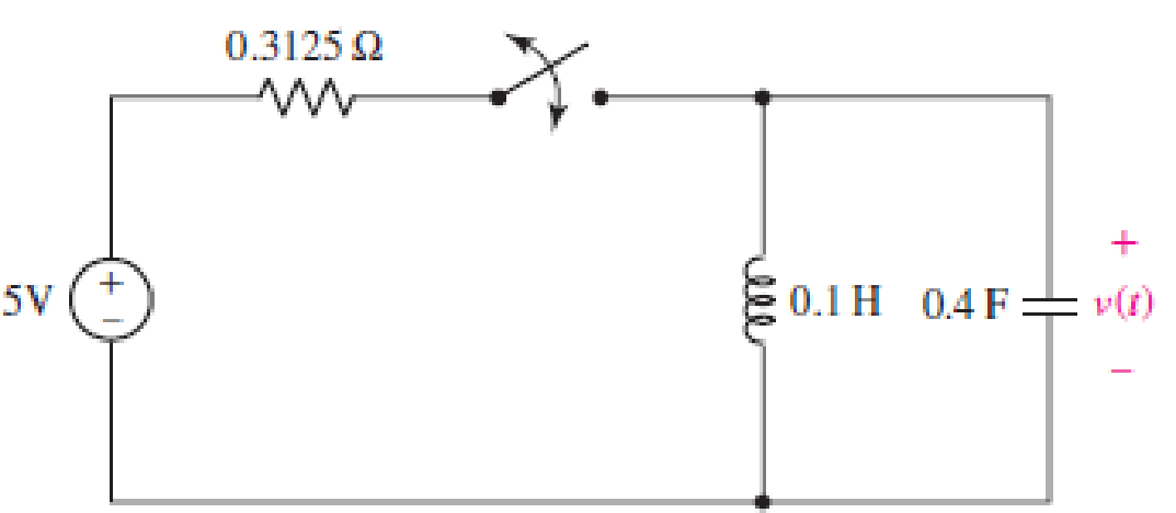
■ FIGURE 9.62
Expert Solution & Answer

Trending nowThis is a popular solution!

Students have asked these similar questions
Compute the voltage v0(t) at the steady state for E0=6V e1(t)=4cos(t-90)V note that the direction of v0(t) is upwards. wherever i wrote ground means that it is grounded in that position. please soLve this in extreme detail with excesssive explanations on everything as i have an exam tomorrow and i need to understand how to solve problems of this type. thank you! (ignore the wires coming out of the op-amp ) THIS IS NOT A GRADED QUESTION. PLEASE DO NOT REJECT IT AS IF IT IS
The ac bridge shown in Fig. 9.84 is known as a
Maxwell bridge and is used for accurate measurement
of inductance and resistance of a coil in terms of a
standard capacitance C.. Show that when the bridge
is balanced,
R2 R3
R₁
Lx = R₂R3Cs and Rx
=
1.6 ΚΩ,
Find Lx and R, for R₁ = 40 kN, R₂
R3 = 4 kn, and C₂ = 0.45 µF.
R₁
R3
Cs
R₂
AC
meter
R₂
ell
Electrical Engineering
9. Find the solution to the linear constant coeffcient difference equation
(n)= >(n=1)-y(n-2)+ 2u(n) with
(-1)=2
and y(-2)=1.
Chapter 9 Solutions
Loose Leaf for Engineering Circuit Analysis Format: Loose-leaf
Ch. 9.1 - A parallel RLC circuit contains a 100 2 resistor...Ch. 9.2 - After being open for a long time, the switch in...Ch. 9.2 - Prob. 3PCh. 9.2 - Prob. 4PCh. 9.3 - (a) Choose R1 in the circuit of Fig. 9.14 so that...Ch. 9.4 - Prob. 6PCh. 9.5 - Prob. 7PCh. 9.5 - Prob. 8PCh. 9.6 - Let is = 10u(t) 20u(t) A in Fig. 9.31. Find (a)...Ch. 9.6 - Let vs = 10 + 20u(t) V in the circuit of Fig....
Ch. 9.7 - Alter the capacitor value and voltage source in...Ch. 9 - For a certain source-free parallel RLC circuit, R...Ch. 9 - Element values of 10 mF and 2 nH are employed in...Ch. 9 - If a parallel RLC circuit is constructed from...Ch. 9 - Prob. 4ECh. 9 - You go to construct the circuit in Exercise 1,...Ch. 9 - A parallel RLC circuit has inductance 2 mH and...Ch. 9 - Prob. 7ECh. 9 - A parallel RLC circuit has R = 1 k, L = 50 mH. and...Ch. 9 - Prob. 9ECh. 9 - Prob. 10ECh. 9 - The current flowing through a 5 resistor in a...Ch. 9 - For the circuit of Fig.9.40, obtain an expression...Ch. 9 - Consider the circuit depicted in Fig. 9.40. (a)...Ch. 9 - With regard to the circuit represented in Fig....Ch. 9 - (a) Assuming the passive sign convention, obtain...Ch. 9 - With regard to the circuit presented in Fig. 9.42,...Ch. 9 - Obtain expressions for the current i(t) and...Ch. 9 - FIGURE 9.43 Replace the 14 resistor in the...Ch. 9 - Design a complete source-free parallel RLC circuit...Ch. 9 - For the circuit represented by Fig. 9.44, the two...Ch. 9 - Prob. 21ECh. 9 - Prob. 22ECh. 9 - A critically damped parallel RLC circuit is...Ch. 9 - A source-free parallel RLC circuit has an initial...Ch. 9 - A critically damped parallel RLC circuit is...Ch. 9 - For the circuit of Fig. 9.45, is(t) = 30u(t) mA....Ch. 9 - Prob. 27ECh. 9 - The circuit of Fig. 9.44 is rebuilt such that the...Ch. 9 - Prob. 29ECh. 9 - Prob. 30ECh. 9 - The source-free circuit depicted in Fig. 9.1 is...Ch. 9 - (a) Graph the current i for the circuit described...Ch. 9 - Analyze the circuit described in Exercise 31 to...Ch. 9 - A source-free parallel RLC circuit has capacitance...Ch. 9 - Prob. 35ECh. 9 - Obtain an expression for vL(t), t 0, for the...Ch. 9 - For the circuit of Fig. 9.47, determine (a) the...Ch. 9 - (a) Design a parallel RLC circuit that provides a...Ch. 9 - The circuit depicted in Fig. 9.48 is just barely...Ch. 9 - When constructing the circuit of Fig. 9.48, you...Ch. 9 - The circuit of Fig. 9.22a is constructed with a...Ch. 9 - Prob. 42ECh. 9 - Prob. 43ECh. 9 - The simple three-element series RLC circuit of...Ch. 9 - Prob. 45ECh. 9 - Prob. 46ECh. 9 - Prob. 47ECh. 9 - With reference to the series RLC circuit of Fig....Ch. 9 - Obtain an expression for i1 as labeled in Fig....Ch. 9 - The circuit in Fig. 9.52 has the switch in...Ch. 9 - For the circuit in Fig. 9.52, determine the value...Ch. 9 - In the series circuit of Fig. 9.53, set R = 1 ....Ch. 9 - Evaluate the derivative of each current and...Ch. 9 - Consider the circuit depicted in Fig. 9.55. If...Ch. 9 - Prob. 55ECh. 9 - In the circuit shown in Fig. 9.56, (a) obtain an...Ch. 9 - Prob. 57ECh. 9 - For the circuit represented in Fig. 9.57, (a)...Ch. 9 - FIGURE 9.57 Replace the 1 resistor in Fig. 9.57...Ch. 9 - A circuit has an inductive load of 2 H, a...Ch. 9 - (a) Adjust the value of the 3 resistor in the...Ch. 9 - Determine expressions for vC(t) and iL(t) in Fig....Ch. 9 - The capacitor in the LC circuit in Fig. 9.60 has...Ch. 9 - Suppose that the switch in the circuit in Fig....Ch. 9 - The capacitor in the circuit of Fig. 9.63 is set...Ch. 9 - The physical behavior of automotive suspension...Ch. 9 - A lossless LC circuit can be used to provide...
Knowledge Booster


Learn more about
Need a deep-dive on the concept behind this application? Look no further. Learn more about this topic, electrical-engineering and related others by exploring similar questions and additional content below.Similar questions
- H = 3RM2cos(9ft) where f = frequency, t = time, and the remaining variables are either proportionality constants or material constants. What is the maximum value H could have (algebraic answer)arrow_forwarda) i) Sketch the sequence x[n] = only go from n = -2 to n = +3). State whether x[n] is even or odd. sin(n. T/2) plotted against 'n' (the sketch should %3Darrow_forwardPlease solve Urgent. I give upvote. An equation of voltage V(t)=10e^-5t applied at time 0 to a R - L series circuit. Obtain particular solution for the current i(t) for t>0.1arrow_forward
- For function f(t) = 5 sin(2t) show analytically & graphically the function form subject to shift upwards by 5 units shift in time domain by 5 units left. Please answer in typing format and draw diagram on paper and cleanarrow_forwardL=850mH C=280uF For circuit; a) Find the time constant for t> 0. b) Find the equation for i0 (t) for time t> 0. c) Find the equation V0 (t) for time t> 0.arrow_forwardPlease answer ASAP and I'll upvote, thank you. In the given circuit, switch S1 is in position A and switch S2 is open. Both switches are in these states for a very long time. At t=0, switch S1 moves from position A to B while switch S2remains open. 10ms after switch S1 moves to position B, switch S2 is closed and remains closed for 20ms only. Determine the expressions for the inductor current for 0≤t<10ms, 10ms≤t<30ms, 30ms≤t<∞, and determine the time (in ms) after switch S1 moves to position B is the current in the inductor equivalent to 30% of the initial value (at ?=0).arrow_forward
- The natural response is the behavior of a circuit for a long time when an external excitation is applied. True Falsearrow_forwardPart (0) Prior to coming to the lab, calculate the theoretical parameter values of S₁, S2, a, wd and T (time period) for the RLC circuit shown in Figure 9.1 and record them in Table 9.1 + 2Vp-p ( Figure 9.1: Series RLC Circuit α Rtot 2009 m Wo 100mH Table 9.1: Theoretical Parameter Values of Figure 9.1 Parameter Calculated Value Wd S₁ S₂ T 39 0.01μFarrow_forwardThe circuit was in steady state at t=0-. The switch closes at t= 0. Write expressions for I. (t>0), and V. (t> 0). Also, sketch I (t> 0) and V. (t> 0). ve v t=0 wwwww 252 +m² ^ www 1.5 13 ↑ IOAarrow_forward
- Question 6 Given a formula for i(t)=10sin(200pit+pi/8) across a capacitor (C=5microfarads). Find the expression of the voltage v(t) across the capcitor. Where Im confused is after integrating the Current and dividing it by C=5microfarads do we need to add +K at the end of the expression? Full explainthe this question very fast solution sent me step by step Don't ignore any part all part work u Text typing work only not allow paper work ......arrow_forwardR1 Bt=T. R3 V1 A vc(t) V2 R2 Given To=2 secs V1=15 V V2=11 V C = 4 F R1=13 N R2=10 Q R3=14 2 and that the voltage across the capacitor is vc(t) = vc(∞) + (Vc(To†) - vC))eT/T for t> To+. Determine the Note that t=RTHC where RTh is the Thevenin equivalent resistance that the time constant t in seconds. capacitor sees after the switch moves from position A to position B at To secs. Find the time constant t in secs. Round your answer to the nearest single digit decimal place.arrow_forwardIn a series RC circuit, R = 5 ohms, C = 0.01 Farad, and E = 100 volts. When t = 0, i = 0. Find the charge at any time t. APPLY THE LAWS OF FIRST ORDER LINEAR DIFFERENTIAL EQUATIONarrow_forward
arrow_back_ios
SEE MORE QUESTIONS
arrow_forward_ios
Recommended textbooks for you
 Introductory Circuit Analysis (13th Edition)Electrical EngineeringISBN:9780133923605Author:Robert L. BoylestadPublisher:PEARSON
 Delmar's Standard Textbook Of ElectricityElectrical EngineeringISBN:9781337900348Author:Stephen L. HermanPublisher:Cengage Learning
 Programmable Logic ControllersElectrical EngineeringISBN:9780073373843Author:Frank D. PetruzellaPublisher:McGraw-Hill Education
 Fundamentals of Electric CircuitsElectrical EngineeringISBN:9780078028229Author:Charles K Alexander, Matthew SadikuPublisher:McGraw-Hill Education
 Electric Circuits. (11th Edition)Electrical EngineeringISBN:9780134746968Author:James W. Nilsson, Susan RiedelPublisher:PEARSON
 Engineering ElectromagneticsElectrical EngineeringISBN:9780078028151Author:Hayt, William H. (william Hart), Jr, BUCK, John A.Publisher:Mcgraw-hill Education,
Introductory Circuit Analysis (13th Edition)
Electrical Engineering
ISBN:9780133923605
Author:Robert L. Boylestad
Publisher:PEARSON
Delmar's Standard Textbook Of Electricity
Electrical Engineering
ISBN:9781337900348
Author:Stephen L. Herman
Publisher:Cengage Learning
Programmable Logic Controllers
Electrical Engineering
ISBN:9780073373843
Author:Frank D. Petruzella
Publisher:McGraw-Hill Education
Fundamentals of Electric Circuits
Electrical Engineering
ISBN:9780078028229
Author:Charles K Alexander, Matthew Sadiku
Publisher:McGraw-Hill Education
Electric Circuits. (11th Edition)
Electrical Engineering
ISBN:9780134746968
Author:James W. Nilsson, Susan Riedel
Publisher:PEARSON
Engineering Electromagnetics
Electrical Engineering
ISBN:9780078028151
Author:Hayt, William H. (william Hart), Jr, BUCK, John A.
Publisher:Mcgraw-hill Education,
ECE320 Lecture1-3c: Steady-State Error, System Type; Author: Rose-Hulman Online;https://www.youtube.com/watch?v=hG7dq-51AAg;License: Standard Youtube License