
Loose Leaf for Engineering Circuit Analysis Format: Loose-leaf
9th Edition
ISBN: 9781259989452
Author: Hayt
Publisher: Mcgraw Hill Publishers
expand_more
expand_more
format_list_bulleted
Videos
Textbook Question
Chapter 9, Problem 53E
Evaluate the derivative of each current and voltage variable labeled in Fig. 9.54 at t = 0+.
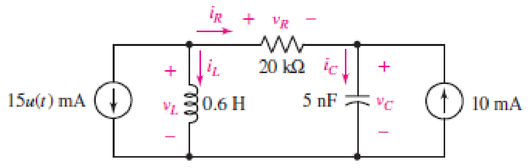
■ FIGURE 9.54
Expert Solution & Answer
Want to see the full answer?
Check out a sample textbook solution
Students have asked these similar questions
Electrical Engineering
9. Find the solution to the linear constant coeffcient difference equation
(n)= >(n=1)-y(n-2)+ 2u(n) with
(-1)=2
and y(-2)=1.
The ac bridge shown in Fig. 9.84 is known as a
Maxwell bridge and is used for accurate measurement
of inductance and resistance of a coil in terms of a
standard capacitance C.. Show that when the bridge
is balanced,
R2 R3
R₁
Lx = R₂R3Cs and Rx
=
1.6 ΚΩ,
Find Lx and R, for R₁ = 40 kN, R₂
R3 = 4 kn, and C₂ = 0.45 µF.
R₁
R3
Cs
R₂
AC
meter
R₂
ell
9.
+.
For the circuit shown in the figure next, and
assuming that the network has been operating
for a long time, the value of the energy
stored in the inductor is found to be (in Joules)
4 F
3 0
6 A
6Ω
5H
Figure Y1
None of the choices
40
90
10
O 810
Chapter 9 Solutions
Loose Leaf for Engineering Circuit Analysis Format: Loose-leaf
Ch. 9.1 - A parallel RLC circuit contains a 100 2 resistor...Ch. 9.2 - After being open for a long time, the switch in...Ch. 9.2 - Prob. 3PCh. 9.2 - Prob. 4PCh. 9.3 - (a) Choose R1 in the circuit of Fig. 9.14 so that...Ch. 9.4 - Prob. 6PCh. 9.5 - Prob. 7PCh. 9.5 - Prob. 8PCh. 9.6 - Let is = 10u(t) 20u(t) A in Fig. 9.31. Find (a)...Ch. 9.6 - Let vs = 10 + 20u(t) V in the circuit of Fig....
Ch. 9.7 - Alter the capacitor value and voltage source in...Ch. 9 - For a certain source-free parallel RLC circuit, R...Ch. 9 - Element values of 10 mF and 2 nH are employed in...Ch. 9 - If a parallel RLC circuit is constructed from...Ch. 9 - Prob. 4ECh. 9 - You go to construct the circuit in Exercise 1,...Ch. 9 - A parallel RLC circuit has inductance 2 mH and...Ch. 9 - Prob. 7ECh. 9 - A parallel RLC circuit has R = 1 k, L = 50 mH. and...Ch. 9 - Prob. 9ECh. 9 - Prob. 10ECh. 9 - The current flowing through a 5 resistor in a...Ch. 9 - For the circuit of Fig.9.40, obtain an expression...Ch. 9 - Consider the circuit depicted in Fig. 9.40. (a)...Ch. 9 - With regard to the circuit represented in Fig....Ch. 9 - (a) Assuming the passive sign convention, obtain...Ch. 9 - With regard to the circuit presented in Fig. 9.42,...Ch. 9 - Obtain expressions for the current i(t) and...Ch. 9 - FIGURE 9.43 Replace the 14 resistor in the...Ch. 9 - Design a complete source-free parallel RLC circuit...Ch. 9 - For the circuit represented by Fig. 9.44, the two...Ch. 9 - Prob. 21ECh. 9 - Prob. 22ECh. 9 - A critically damped parallel RLC circuit is...Ch. 9 - A source-free parallel RLC circuit has an initial...Ch. 9 - A critically damped parallel RLC circuit is...Ch. 9 - For the circuit of Fig. 9.45, is(t) = 30u(t) mA....Ch. 9 - Prob. 27ECh. 9 - The circuit of Fig. 9.44 is rebuilt such that the...Ch. 9 - Prob. 29ECh. 9 - Prob. 30ECh. 9 - The source-free circuit depicted in Fig. 9.1 is...Ch. 9 - (a) Graph the current i for the circuit described...Ch. 9 - Analyze the circuit described in Exercise 31 to...Ch. 9 - A source-free parallel RLC circuit has capacitance...Ch. 9 - Prob. 35ECh. 9 - Obtain an expression for vL(t), t 0, for the...Ch. 9 - For the circuit of Fig. 9.47, determine (a) the...Ch. 9 - (a) Design a parallel RLC circuit that provides a...Ch. 9 - The circuit depicted in Fig. 9.48 is just barely...Ch. 9 - When constructing the circuit of Fig. 9.48, you...Ch. 9 - The circuit of Fig. 9.22a is constructed with a...Ch. 9 - Prob. 42ECh. 9 - Prob. 43ECh. 9 - The simple three-element series RLC circuit of...Ch. 9 - Prob. 45ECh. 9 - Prob. 46ECh. 9 - Prob. 47ECh. 9 - With reference to the series RLC circuit of Fig....Ch. 9 - Obtain an expression for i1 as labeled in Fig....Ch. 9 - The circuit in Fig. 9.52 has the switch in...Ch. 9 - For the circuit in Fig. 9.52, determine the value...Ch. 9 - In the series circuit of Fig. 9.53, set R = 1 ....Ch. 9 - Evaluate the derivative of each current and...Ch. 9 - Consider the circuit depicted in Fig. 9.55. If...Ch. 9 - Prob. 55ECh. 9 - In the circuit shown in Fig. 9.56, (a) obtain an...Ch. 9 - Prob. 57ECh. 9 - For the circuit represented in Fig. 9.57, (a)...Ch. 9 - FIGURE 9.57 Replace the 1 resistor in Fig. 9.57...Ch. 9 - A circuit has an inductive load of 2 H, a...Ch. 9 - (a) Adjust the value of the 3 resistor in the...Ch. 9 - Determine expressions for vC(t) and iL(t) in Fig....Ch. 9 - The capacitor in the LC circuit in Fig. 9.60 has...Ch. 9 - Suppose that the switch in the circuit in Fig....Ch. 9 - The capacitor in the circuit of Fig. 9.63 is set...Ch. 9 - The physical behavior of automotive suspension...Ch. 9 - A lossless LC circuit can be used to provide...
Knowledge Booster


Learn more about
Need a deep-dive on the concept behind this application? Look no further. Learn more about this topic, electrical-engineering and related others by exploring similar questions and additional content below.Similar questions
- Obtain an equation for vc as labeled in the circuit of Fig. 9.48 valid for all t > 0. 1 = 0 2i + VC 100 2 40 μF 9 V 30 N 90 mH FIGURE 9.48 47. Vc(t) = -2.08e-1188.4986t + 10.48e-233.721t %3D ellarrow_forwardFor V1=79 & 11=0.007, the voltage and current expressions are: (take care of the units) v = vie-500t V, t> 0; i = = 11e-500t A, t 20*. R Find the following: R= T(tau)= C= The initial energy stored in the capacitor=arrow_forwardH = 3RM2cos(9ft) where f = frequency, t = time, and the remaining variables are either proportionality constants or material constants. What is the maximum value H could have (algebraic answer)arrow_forward
- For the circuit shown in the figure, the switch changes from position 1 to position 2 at t=0 s for a t=1.8s, determine the value of the voltage across the capacitor. www. R-30 Ohms 20V 1 290 0,25 F 4H 10 Ohmsarrow_forwardThe current through a 20-mH inductor is shown in Fig. 9. Sketch the voltage across the inductor. i(t) (A) 10 -10 0 1 2 Figure 9 3 4arrow_forwardFor V1=71 & 11=0.005, the voltage and current expressions are: (take care of the units) v = vie-50ot v, t > 0; i = Il e-500t A, t 0+. v R$ Find the following: R= T(tau)= C= The initial energy stored in the capacitor=arrow_forward
- Given That: Is=0.0098, R1=60000, R2=6000 0, L=16 H, C=2 F, The circuit shown below under dc conditions find the following: L ell Is R1 R2 the current in L The voltage across capacitorarrow_forward1. Consider the following circuit and answer the corresponding questions: t=0 300 100 2A Vo 100 100 1uH :36pF 1lai general solifion ev ... or **V 74 . Qualitatively sketch the capacitor voltage "Vc(t)" as a function of time between -0arrow_forwardFIGURE 9.45 27. The inductor in the circuit of Fig. 9.43 is changed such that the circuit response is now critically damped. (a) Determine the new inductor value. (b) Calculate the energy stored in both the inductor and the capacitor at t = 10 ms. 30 787arrow_forwardThe starting voltage of the C = 0.05 microfarad capacitor given in the figure is V0 = 30 Volts and the starting current of the coil is I0 = 0 amperes. in this case the voltage response of the circuit; For t> = 0, since V (t) = - 10 e-5000 + 40e-20000 volts, iL (t) current iL (t) current t = 0.0003 mA per second.arrow_forwardS:46) I just need the integral of the mutual inductance for these 3 problemsarrow_forwardWith reference to the figure below, sketch the inductor voltage, vL, as a function of time, 0 < t < 60 ms. Solve also for the energy stored on the inductor at t = 40 ms. mV VL1 mV VL2 mV VL3 mV VL4 WL iL(A) 0.2 H ell r(ms) 10 20 30 50 60 40arrow_forwardarrow_back_iosSEE MORE QUESTIONSarrow_forward_ios
Recommended textbooks for you
 Introductory Circuit Analysis (13th Edition)Electrical EngineeringISBN:9780133923605Author:Robert L. BoylestadPublisher:PEARSON
 Delmar's Standard Textbook Of ElectricityElectrical EngineeringISBN:9781337900348Author:Stephen L. HermanPublisher:Cengage Learning
 Programmable Logic ControllersElectrical EngineeringISBN:9780073373843Author:Frank D. PetruzellaPublisher:McGraw-Hill Education
 Fundamentals of Electric CircuitsElectrical EngineeringISBN:9780078028229Author:Charles K Alexander, Matthew SadikuPublisher:McGraw-Hill Education
 Electric Circuits. (11th Edition)Electrical EngineeringISBN:9780134746968Author:James W. Nilsson, Susan RiedelPublisher:PEARSON
 Engineering ElectromagneticsElectrical EngineeringISBN:9780078028151Author:Hayt, William H. (william Hart), Jr, BUCK, John A.Publisher:Mcgraw-hill Education,
Introductory Circuit Analysis (13th Edition)
Electrical Engineering
ISBN:9780133923605
Author:Robert L. Boylestad
Publisher:PEARSON
Delmar's Standard Textbook Of Electricity
Electrical Engineering
ISBN:9781337900348
Author:Stephen L. Herman
Publisher:Cengage Learning
Programmable Logic Controllers
Electrical Engineering
ISBN:9780073373843
Author:Frank D. Petruzella
Publisher:McGraw-Hill Education
Fundamentals of Electric Circuits
Electrical Engineering
ISBN:9780078028229
Author:Charles K Alexander, Matthew Sadiku
Publisher:McGraw-Hill Education
Electric Circuits. (11th Edition)
Electrical Engineering
ISBN:9780134746968
Author:James W. Nilsson, Susan Riedel
Publisher:PEARSON
Engineering Electromagnetics
Electrical Engineering
ISBN:9780078028151
Author:Hayt, William H. (william Hart), Jr, BUCK, John A.
Publisher:Mcgraw-hill Education,
Routh Hurwitz Stability Criterion Basic Worked Example; Author: The Complete Guide to Everything;https://www.youtube.com/watch?v=CzzsR5FT-8U;License: Standard Youtube License