
Loose Leaf for Engineering Circuit Analysis Format: Loose-leaf
9th Edition
ISBN: 9781259989452
Author: Hayt
Publisher: Mcgraw Hill Publishers
expand_more
expand_more
format_list_bulleted
Concept explainers
Videos
Textbook Question
Chapter 9, Problem 18E
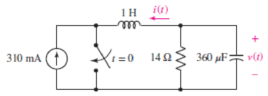
■ FIGURE 9.43
Replace the 14 Ω resistor in the circuit of Fig. 9.43 with a 1 Ω resistor. (a) Obtain an expression for the energy stored in the capacitor as a function of time, valid for t > 0. (b) Determine the time at which the energy in the capacitor has been reduced to one-half its maximum value. (c) Verify your answer with an appropriate SPICE simulation.
Expert Solution & Answer
Want to see the full answer?
Check out a sample textbook solution
Students have asked these similar questions
9.pdf - Adobe Acrobat Reader DC (64-bit)
ndow Help
FINAL EP QP_SEM . x
Sign In
10 / 12
116%
Search Combine PDF
Export PDF
A capacitor is charged with 50 mC in a time of 20 uS. If the energy stored in the capacitor is 5 J,
Edit PDF
find (i) voltage across the capacitor, (ii) current through the capacitor and (iii) value of capacitance.
Create PDF
EComment
Combine Files
E0 Organize Pag
Delete, insert, extract and
rotate pages.
Try now
Convert, edit and e-sign P
J01] The current in a 150 µH inductor is known to be as follows:
iL = 25te SON
A for t 0.
%3D
a) Find the voltage across the inductor for t>0 (Assume the passive sign convention.).
b) Find the power (in microwatts) at the terminals of the inductor when t = 5 ms.
c) Is the inductor absorbing or delivering power at 5 ms?
d) Find the energy (in microjoules) stored in the inductor at 5 ms.
e) Find the maximum energy (in µJ) stored in the inductor & the time (in ms) when it occurs.
c) Represent the following signal in Figure Q1(c) in terms of sum of singularity
function and sketch its integration.
x(t)
1
3
8.
Figure Q1(c)
Chapter 9 Solutions
Loose Leaf for Engineering Circuit Analysis Format: Loose-leaf
Ch. 9.1 - A parallel RLC circuit contains a 100 2 resistor...Ch. 9.2 - After being open for a long time, the switch in...Ch. 9.2 - Prob. 3PCh. 9.2 - Prob. 4PCh. 9.3 - (a) Choose R1 in the circuit of Fig. 9.14 so that...Ch. 9.4 - Prob. 6PCh. 9.5 - Prob. 7PCh. 9.5 - Prob. 8PCh. 9.6 - Let is = 10u(t) 20u(t) A in Fig. 9.31. Find (a)...Ch. 9.6 - Let vs = 10 + 20u(t) V in the circuit of Fig....
Ch. 9.7 - Alter the capacitor value and voltage source in...Ch. 9 - For a certain source-free parallel RLC circuit, R...Ch. 9 - Element values of 10 mF and 2 nH are employed in...Ch. 9 - If a parallel RLC circuit is constructed from...Ch. 9 - Prob. 4ECh. 9 - You go to construct the circuit in Exercise 1,...Ch. 9 - A parallel RLC circuit has inductance 2 mH and...Ch. 9 - Prob. 7ECh. 9 - A parallel RLC circuit has R = 1 k, L = 50 mH. and...Ch. 9 - Prob. 9ECh. 9 - Prob. 10ECh. 9 - The current flowing through a 5 resistor in a...Ch. 9 - For the circuit of Fig.9.40, obtain an expression...Ch. 9 - Consider the circuit depicted in Fig. 9.40. (a)...Ch. 9 - With regard to the circuit represented in Fig....Ch. 9 - (a) Assuming the passive sign convention, obtain...Ch. 9 - With regard to the circuit presented in Fig. 9.42,...Ch. 9 - Obtain expressions for the current i(t) and...Ch. 9 - FIGURE 9.43 Replace the 14 resistor in the...Ch. 9 - Design a complete source-free parallel RLC circuit...Ch. 9 - For the circuit represented by Fig. 9.44, the two...Ch. 9 - Prob. 21ECh. 9 - Prob. 22ECh. 9 - A critically damped parallel RLC circuit is...Ch. 9 - A source-free parallel RLC circuit has an initial...Ch. 9 - A critically damped parallel RLC circuit is...Ch. 9 - For the circuit of Fig. 9.45, is(t) = 30u(t) mA....Ch. 9 - Prob. 27ECh. 9 - The circuit of Fig. 9.44 is rebuilt such that the...Ch. 9 - Prob. 29ECh. 9 - Prob. 30ECh. 9 - The source-free circuit depicted in Fig. 9.1 is...Ch. 9 - (a) Graph the current i for the circuit described...Ch. 9 - Analyze the circuit described in Exercise 31 to...Ch. 9 - A source-free parallel RLC circuit has capacitance...Ch. 9 - Prob. 35ECh. 9 - Obtain an expression for vL(t), t 0, for the...Ch. 9 - For the circuit of Fig. 9.47, determine (a) the...Ch. 9 - (a) Design a parallel RLC circuit that provides a...Ch. 9 - The circuit depicted in Fig. 9.48 is just barely...Ch. 9 - When constructing the circuit of Fig. 9.48, you...Ch. 9 - The circuit of Fig. 9.22a is constructed with a...Ch. 9 - Prob. 42ECh. 9 - Prob. 43ECh. 9 - The simple three-element series RLC circuit of...Ch. 9 - Prob. 45ECh. 9 - Prob. 46ECh. 9 - Prob. 47ECh. 9 - With reference to the series RLC circuit of Fig....Ch. 9 - Obtain an expression for i1 as labeled in Fig....Ch. 9 - The circuit in Fig. 9.52 has the switch in...Ch. 9 - For the circuit in Fig. 9.52, determine the value...Ch. 9 - In the series circuit of Fig. 9.53, set R = 1 ....Ch. 9 - Evaluate the derivative of each current and...Ch. 9 - Consider the circuit depicted in Fig. 9.55. If...Ch. 9 - Prob. 55ECh. 9 - In the circuit shown in Fig. 9.56, (a) obtain an...Ch. 9 - Prob. 57ECh. 9 - For the circuit represented in Fig. 9.57, (a)...Ch. 9 - FIGURE 9.57 Replace the 1 resistor in Fig. 9.57...Ch. 9 - A circuit has an inductive load of 2 H, a...Ch. 9 - (a) Adjust the value of the 3 resistor in the...Ch. 9 - Determine expressions for vC(t) and iL(t) in Fig....Ch. 9 - The capacitor in the LC circuit in Fig. 9.60 has...Ch. 9 - Suppose that the switch in the circuit in Fig....Ch. 9 - The capacitor in the circuit of Fig. 9.63 is set...Ch. 9 - The physical behavior of automotive suspension...Ch. 9 - A lossless LC circuit can be used to provide...
Knowledge Booster


Learn more about
Need a deep-dive on the concept behind this application? Look no further. Learn more about this topic, electrical-engineering and related others by exploring similar questions and additional content below.Similar questions
- 9. 7.92. b) Suppose the inductor you chose in part (a) has an initial currentof 10 mA. Write an expression for the current through the inductorfor t≥0.arrow_forwardA10,000μF capacitor has an asymmetric tolerance specification of+20%/−50%.What is the possible range of values for this capacitor?F capacitor has an asymmetric tolerance specificationof+20%/−50%.Whatisthepossible range of values for this capacitor?arrow_forward10. The sketch (right side) shows a simple RC circuit. The capacitor is initially uncharged, and at t=0 the switch S is closed. Express your answers in terms of Vo, R1, R2 and C. Rz a) Determine the current through each resistor immediately after the switch is closed. b) Determine the charge on the capacitor Q(t) as a function of time after the switch is closed. What are the initial charge Q(t=0), the final charge Q(t -> ∞), and the time constant? Sketch Q(t) vs. t. c) Determine the current through the capacitor I(t) as a function of time after the switch is closed. What are the initial current I(t=0), the final current I(t-> ∞) and the time constant? Sketch I(t) vs. t.arrow_forward
- 9. The voltage across a 2200-pF capacitor is vc(t) = 50 cos (2n10ªt) V. Derive expressions for ic(t) and pc(t). Is the capacitor absorbing power, delivering power, or both? Explain. Solution:arrow_forwardplease could you solve this problem in a simple way and thank you^^ A 7.9 micro-Farad capacitor was initially chargedto 10V and connected to a 9.3 kilo-Ohm resistorand a switch. The switch is then closed at t=0allowing the capacitor to discharge.The time needed for the voltage on the capacitorto reach 5V is (in milliseconds):a. 0.01b. 36.74c. 73.47d. 253. 47e. 50.69arrow_forwardTask: Using the given charge and discharge values at these discrete points in time, construct two plots of Voltage (V.) vs. Time (t) for charging and discharging of the capacitor. ID: Name of Student: 3.1 RC Circuit The objective of this part is to study the charging and discharging of a capacitor by measuring the potential difference (voltage) across the capacitor as a function of time. The students will also measure the experimental time constant and use it to determine the experimental value of the capacitance of the capacitor. Table 1. Voltage-Time Table for Charging Capacitor Time t(s) Potential Diffèrence V(t) Time t(s) Potential Diffèrence V(t) 40 1.328 V OV 5 0.332 V 50 1.386 V 10 60 0.638 V 1.422 V 15 70 0.861 V 1.437 V 20 1.017 V 80 1.448 V | 25 90 1.458 V 1.131 V Task: Using your collected Voltage-Time data for discharging, calculate time constant t. 30 1.220 V 100 1.458 V Show the formulations and data pair you used in the calculation. If the resistance is given to be equal…arrow_forward
- Problem 2 The voltage across a 2-F capacitor is shown in the given figure. Sketch versus time the capacitor a) current b) power c) stored energy v(t) 3 t (s) 0.1 0.2 0.3 0.4arrow_forwardA 0.8-F capacitor is connected in series with a 7-ohm resistor. If the connection is energized from a 10-V DC source, determine the voltage (in volts) across the capacitor at t = 2.5 ms. The initial charge is 150 mC. Express your answers accurate to four decimal places. No need to put the units. Do not put spaces.arrow_forwardThe circuit of Fig. 9.2 is modified substantially, with the resistor being re- placed with a 1 k resistor, the inductor swapped out for a smaller 7 mH ver- sion, the capacitor replaced with a 1 nF alternative, and now the inductor is ini- tially discharged while the capacitor is storing 7.2 mJ. (a) Compute a, wo, $1, and $2, and verify that the circuit is still overdamped. (b) Obtain an expression for the current flowing through the resistor which is valid for t > 0. (c) Calcu- late the magnitude of the resistor current at t = 10 µs. 6Ω 7 H v FIGURE 9.2 A parallel RLC circuit used as a numer- ical example. The circuit is overdamped.arrow_forward
- Find the charge q(t) on the capacitor and the current i(t) in the given LRC-series circuit. L = 1 h, R = 100 2, c = 0.0004 f, E(t) = 40 V, q(0) = 0 C, i(0) = 2 A q(t) i(t) A Find the maximum charge on the capacitor. (Round your answer to four decimal places.)arrow_forwardThe voltage across a 5 µF capacitor is known to be Ve = 500te-2500t V for t > 0. a. Find the current through the capacitor for t > 0. Assume the passive sign convention. b. Find the power at the terminals of the capacitor when t = 100 µus. c. Is the capacitor absorbing or delivering power at t = 100 us ? d. Find the energy stored in the capacitor at t = 100 us. e. Find the maximum energy stored in the capacitors and the time when the maximum occurs.arrow_forwardGROUP 8 LRC series circuit connected in series with resistance of 4 ohms, a capacitor of 26 farad and an inductance of ½ henry has an applied voltage E(t) = 16 cos 2t. There is no initial current and no initial charge on the capacitor' a) Find the expression for the current I(t) flowing through the circuit at any time t b) If the applied voltage is removed, what will happen to the current flow after a long time? c) If the applied voltage is charged to E(t)-16 cos 6t, what will happen to the current flow?arrow_forward
arrow_back_ios
SEE MORE QUESTIONS
arrow_forward_ios
Recommended textbooks for you
 Introductory Circuit Analysis (13th Edition)Electrical EngineeringISBN:9780133923605Author:Robert L. BoylestadPublisher:PEARSON
 Delmar's Standard Textbook Of ElectricityElectrical EngineeringISBN:9781337900348Author:Stephen L. HermanPublisher:Cengage Learning
 Programmable Logic ControllersElectrical EngineeringISBN:9780073373843Author:Frank D. PetruzellaPublisher:McGraw-Hill Education
 Fundamentals of Electric CircuitsElectrical EngineeringISBN:9780078028229Author:Charles K Alexander, Matthew SadikuPublisher:McGraw-Hill Education
 Electric Circuits. (11th Edition)Electrical EngineeringISBN:9780134746968Author:James W. Nilsson, Susan RiedelPublisher:PEARSON
 Engineering ElectromagneticsElectrical EngineeringISBN:9780078028151Author:Hayt, William H. (william Hart), Jr, BUCK, John A.Publisher:Mcgraw-hill Education,
Introductory Circuit Analysis (13th Edition)
Electrical Engineering
ISBN:9780133923605
Author:Robert L. Boylestad
Publisher:PEARSON
Delmar's Standard Textbook Of Electricity
Electrical Engineering
ISBN:9781337900348
Author:Stephen L. Herman
Publisher:Cengage Learning
Programmable Logic Controllers
Electrical Engineering
ISBN:9780073373843
Author:Frank D. Petruzella
Publisher:McGraw-Hill Education
Fundamentals of Electric Circuits
Electrical Engineering
ISBN:9780078028229
Author:Charles K Alexander, Matthew Sadiku
Publisher:McGraw-Hill Education
Electric Circuits. (11th Edition)
Electrical Engineering
ISBN:9780134746968
Author:James W. Nilsson, Susan Riedel
Publisher:PEARSON
Engineering Electromagnetics
Electrical Engineering
ISBN:9780078028151
Author:Hayt, William H. (william Hart), Jr, BUCK, John A.
Publisher:Mcgraw-hill Education,
ENA 9.2(1)(En)(Alex) Sinusoids & Phasors - Explanation with Example 9.1 ,9.2 & PP 9.2; Author: Electrical Engineering Academy;https://www.youtube.com/watch?v=vX_LLNl-ZpU;License: Standard YouTube License, CC-BY
Electrical Engineering: Ch 10 Alternating Voltages & Phasors (8 of 82) What is a Phasor?; Author: Michel van Biezen;https://www.youtube.com/watch?v=2I1tF3ixNg0;License: Standard Youtube License