
Loose Leaf for Engineering Circuit Analysis Format: Loose-leaf
9th Edition
ISBN: 9781259989452
Author: Hayt
Publisher: Mcgraw Hill Publishers
expand_more
expand_more
format_list_bulleted
Concept explainers
Videos
Textbook Question
Chapter 9, Problem 58E
For the circuit represented in Fig. 9.57, (a) obtain an expression for vC(t) valid for all t > 0. (b) Determine vC at t = 10 ms and t = 600 ms. (c) Verify your answers to part (b) with an appropriate SPICE simulation.
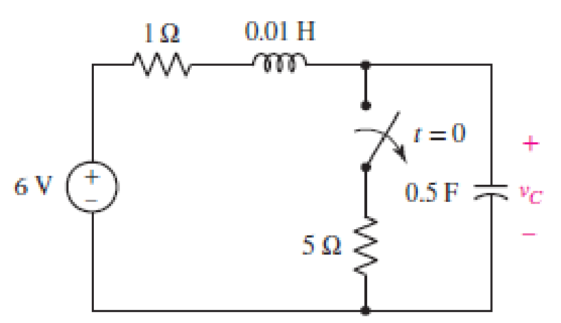
■ FIGURE 9.57
Expert Solution & Answer
Want to see the full answer?
Check out a sample textbook solution
Students have asked these similar questions
The natural response is the behavior of a circuit for a long time when an external excitation is applied.
True
False
For the circuit in Figure 3 the switch is in the left position
for several minutes:
(a) Find the Initlal voltage, V, on the capacitor just
before the switch is flipped
(b) Find an expression v(t) that describes the voltage
across the 20 N resistor after the switch has been
Figure 3
U 09
flipped to the right
NOTE: Remember what we said in class: use a Circuit-Specific
Equation to get a value you know. Then solve for whatever else
the problem asks for
+50 µF 380 0 20 2
3. We have seen that in a series RLC circuit, Kirchoff's voltage law (VR +VL + Vc = Vs, where
Vs is the supply voltage) leads to a 2nd order differential equation for the current I(t). Let
us now consider a parallel RLC circuit consisting of a 5 H inductor, a 10 F capacitor, and a
0.5 N resistor. At time t = 0 s, there is a supply current Is of 5 A. The supply voltage Vs is
common to all three components. Kirchoff's current law states that IR + IL + Iç = Is.
Chapter 9 Solutions
Loose Leaf for Engineering Circuit Analysis Format: Loose-leaf
Ch. 9.1 - A parallel RLC circuit contains a 100 2 resistor...Ch. 9.2 - After being open for a long time, the switch in...Ch. 9.2 - Prob. 3PCh. 9.2 - Prob. 4PCh. 9.3 - (a) Choose R1 in the circuit of Fig. 9.14 so that...Ch. 9.4 - Prob. 6PCh. 9.5 - Prob. 7PCh. 9.5 - Prob. 8PCh. 9.6 - Let is = 10u(t) 20u(t) A in Fig. 9.31. Find (a)...Ch. 9.6 - Let vs = 10 + 20u(t) V in the circuit of Fig....
Ch. 9.7 - Alter the capacitor value and voltage source in...Ch. 9 - For a certain source-free parallel RLC circuit, R...Ch. 9 - Element values of 10 mF and 2 nH are employed in...Ch. 9 - If a parallel RLC circuit is constructed from...Ch. 9 - Prob. 4ECh. 9 - You go to construct the circuit in Exercise 1,...Ch. 9 - A parallel RLC circuit has inductance 2 mH and...Ch. 9 - Prob. 7ECh. 9 - A parallel RLC circuit has R = 1 k, L = 50 mH. and...Ch. 9 - Prob. 9ECh. 9 - Prob. 10ECh. 9 - The current flowing through a 5 resistor in a...Ch. 9 - For the circuit of Fig.9.40, obtain an expression...Ch. 9 - Consider the circuit depicted in Fig. 9.40. (a)...Ch. 9 - With regard to the circuit represented in Fig....Ch. 9 - (a) Assuming the passive sign convention, obtain...Ch. 9 - With regard to the circuit presented in Fig. 9.42,...Ch. 9 - Obtain expressions for the current i(t) and...Ch. 9 - FIGURE 9.43 Replace the 14 resistor in the...Ch. 9 - Design a complete source-free parallel RLC circuit...Ch. 9 - For the circuit represented by Fig. 9.44, the two...Ch. 9 - Prob. 21ECh. 9 - Prob. 22ECh. 9 - A critically damped parallel RLC circuit is...Ch. 9 - A source-free parallel RLC circuit has an initial...Ch. 9 - A critically damped parallel RLC circuit is...Ch. 9 - For the circuit of Fig. 9.45, is(t) = 30u(t) mA....Ch. 9 - Prob. 27ECh. 9 - The circuit of Fig. 9.44 is rebuilt such that the...Ch. 9 - Prob. 29ECh. 9 - Prob. 30ECh. 9 - The source-free circuit depicted in Fig. 9.1 is...Ch. 9 - (a) Graph the current i for the circuit described...Ch. 9 - Analyze the circuit described in Exercise 31 to...Ch. 9 - A source-free parallel RLC circuit has capacitance...Ch. 9 - Prob. 35ECh. 9 - Obtain an expression for vL(t), t 0, for the...Ch. 9 - For the circuit of Fig. 9.47, determine (a) the...Ch. 9 - (a) Design a parallel RLC circuit that provides a...Ch. 9 - The circuit depicted in Fig. 9.48 is just barely...Ch. 9 - When constructing the circuit of Fig. 9.48, you...Ch. 9 - The circuit of Fig. 9.22a is constructed with a...Ch. 9 - Prob. 42ECh. 9 - Prob. 43ECh. 9 - The simple three-element series RLC circuit of...Ch. 9 - Prob. 45ECh. 9 - Prob. 46ECh. 9 - Prob. 47ECh. 9 - With reference to the series RLC circuit of Fig....Ch. 9 - Obtain an expression for i1 as labeled in Fig....Ch. 9 - The circuit in Fig. 9.52 has the switch in...Ch. 9 - For the circuit in Fig. 9.52, determine the value...Ch. 9 - In the series circuit of Fig. 9.53, set R = 1 ....Ch. 9 - Evaluate the derivative of each current and...Ch. 9 - Consider the circuit depicted in Fig. 9.55. If...Ch. 9 - Prob. 55ECh. 9 - In the circuit shown in Fig. 9.56, (a) obtain an...Ch. 9 - Prob. 57ECh. 9 - For the circuit represented in Fig. 9.57, (a)...Ch. 9 - FIGURE 9.57 Replace the 1 resistor in Fig. 9.57...Ch. 9 - A circuit has an inductive load of 2 H, a...Ch. 9 - (a) Adjust the value of the 3 resistor in the...Ch. 9 - Determine expressions for vC(t) and iL(t) in Fig....Ch. 9 - The capacitor in the LC circuit in Fig. 9.60 has...Ch. 9 - Suppose that the switch in the circuit in Fig....Ch. 9 - The capacitor in the circuit of Fig. 9.63 is set...Ch. 9 - The physical behavior of automotive suspension...Ch. 9 - A lossless LC circuit can be used to provide...
Knowledge Booster


Learn more about
Need a deep-dive on the concept behind this application? Look no further. Learn more about this topic, electrical-engineering and related others by exploring similar questions and additional content below.Similar questions
- When the system shown in Figure (a) is subjected to a unit-step input, the system output responds as shown in Figure (b) .Determine the values of K and T from the response curve. R(s) K s(Ts + 1) 0.254 3arrow_forwardGet a state space model for the following electrical system. Make sure to clearly define the states and input(s) using state space notation (x1,x2, ... , Xn for state variables, u1, U2, ... , Um for inputs, and so on). There are two outputs: the voltage of the capacitor C, and the current of the inductor L2. It is given that R1 = 5 N, R2 = 3 N, C = 10 F, L1 = 4 H, L2 = 7 H. %3D elll R2 R. Vsarrow_forward9.39 (System Response) For each circuit of Figure P9.39, let R = 102, C = 1F, and L = 1H as needed. (d) Find the response if the input is x(t) = u(t). + x(t) L R Circuit 4 y(t)arrow_forward
- Circuits a) Using the graph theory of the circuit below, draw the state tree and obtain the state equations. b) Find the Vout expression for the values of R=5 Ω, C=2F and L=3H. (Note: The unit of input voltageSolve if it is a step function.)arrow_forward9.pdf - Adobe Acrobat Reader DC (64-bit) ndow Help FINAL EP QP_SEM . x Sign In 10 / 12 116% Search Combine PDF Export PDF A capacitor is charged with 50 mC in a time of 20 uS. If the energy stored in the capacitor is 5 J, Edit PDF find (i) voltage across the capacitor, (ii) current through the capacitor and (iii) value of capacitance. Create PDF EComment Combine Files E0 Organize Pag Delete, insert, extract and rotate pages. Try now Convert, edit and e-sign Parrow_forwardPicture (1) we can see the circuit where L=4mH, C=2uF and Vs is given in picture (2). The question asks the value of İc at t=8ms. Note: The time (t) given in the graph is in mili seconds (ms) TIAarrow_forward
- %ov lI. 2_526511681092295... UNIVERSITY OF SAMARRA COLLEGE OF ENGINEERING ELECTROMECHANICAL ENGINEERING DEPARTMENT NOTE: ANSWER ALL QUESTIONS Q1) In figure below, the switch in the circuit has been in position (1) for a long time. Att= 0, the switch moves to position (2). Find: a) v (t) b) i, (t) for 120. Q2) The uncharged capacitor in the circuit shown in figure is initially switched to terminal (1). Att=0, the switch is moved to position (2), where it remained for (15 ms). After that, the switch is moved to position (3) for (5 ms). Finally, the switech is moved to position (4) for indefinitely. a) Derive the numerical expression for the voltage across the capacitor and the inductor. b) Plot the capacitor voltage and inductor voltage versus time. rookn ='vit) Q3) For the circuit shown in figure below, at V(0) = lv and i, (0) = 10 mA a) Find the initial value of currents in each branch. b) Find the initial value of e) Find the numerical expression of vit). d) Druw v(1). e) Find ig(t),…arrow_forwardPart A: Open circuit and short circuit faults are important in circuit analysis. These are the most common faults for any circuit. Discuss open circuit and short circuit fault in a circuit. Then discuss why do you think capacitor acts as an open circuit, but inductor acts as a short circuit for a DC input. A detail response is required. Part B: Calculate the time constant and voltage v(t) at t=0, 100s, 200s, 500s, 800s for the following circuitarrow_forwardThe current in the circuit in the following figure is known to be i B₁e -2000t cos1500t + B₂e-2000t sin1500t, t ≥ 0. The capacitor has a value of 80 nF; the initial value of the current is 6.5 mA; and the initial voltage on the capacitor is -21 V.(Figure 1) Figure R www D L Io 1 of 1 > + Vo Correct Here we learn how to determine the value of B₁ in the underdamped natural response of a series RLC circuit. Part D Find the value of B2. Express your answer with the appropriate units. ▾ View Available Hint(s) Hint 1. How to determine B2 Find a and wa from the expression for i. Use KVL to determine the initial voltage across the inductor and calculate the initial value of di/dt. Use the obtained values and the value of B₁ to find B2. B₂= 10.5 Submit 01 Provide Feedback mA Previous Answers Request Answer X Incorrect; Try Again; 2 attempts remaining Next >arrow_forward
- In Figure (1) and Figure (2) illustrate the signal x(t) and w(t). Given the signal p(t) as follows: n() = [=(-;+1) - w»] Sketch the signal p(t) and show the stps clearly. Sketch the odd and even part of p(t). (iii) Determine whether the signal p(t) is an energy signal or power signal. (i) (ii)arrow_forwardwww 822 zez 18V(+ +=0 4 H m 252 find i(t) for circuit! use differential dict) +70 in the fol following ~|J F equation approacharrow_forwardFor function f(t) = 5 sin(2t) show analytically & graphically the function form subject to shift upwards by 5 units shift in time domain by 5 units left. Please answer in typing format and draw diagram on paper and cleanarrow_forward
arrow_back_ios
SEE MORE QUESTIONS
arrow_forward_ios
Recommended textbooks for you
 Introductory Circuit Analysis (13th Edition)Electrical EngineeringISBN:9780133923605Author:Robert L. BoylestadPublisher:PEARSON
 Delmar's Standard Textbook Of ElectricityElectrical EngineeringISBN:9781337900348Author:Stephen L. HermanPublisher:Cengage Learning
 Programmable Logic ControllersElectrical EngineeringISBN:9780073373843Author:Frank D. PetruzellaPublisher:McGraw-Hill Education
 Fundamentals of Electric CircuitsElectrical EngineeringISBN:9780078028229Author:Charles K Alexander, Matthew SadikuPublisher:McGraw-Hill Education
 Electric Circuits. (11th Edition)Electrical EngineeringISBN:9780134746968Author:James W. Nilsson, Susan RiedelPublisher:PEARSON
 Engineering ElectromagneticsElectrical EngineeringISBN:9780078028151Author:Hayt, William H. (william Hart), Jr, BUCK, John A.Publisher:Mcgraw-hill Education,
Introductory Circuit Analysis (13th Edition)
Electrical Engineering
ISBN:9780133923605
Author:Robert L. Boylestad
Publisher:PEARSON
Delmar's Standard Textbook Of Electricity
Electrical Engineering
ISBN:9781337900348
Author:Stephen L. Herman
Publisher:Cengage Learning
Programmable Logic Controllers
Electrical Engineering
ISBN:9780073373843
Author:Frank D. Petruzella
Publisher:McGraw-Hill Education
Fundamentals of Electric Circuits
Electrical Engineering
ISBN:9780078028229
Author:Charles K Alexander, Matthew Sadiku
Publisher:McGraw-Hill Education
Electric Circuits. (11th Edition)
Electrical Engineering
ISBN:9780134746968
Author:James W. Nilsson, Susan Riedel
Publisher:PEARSON
Engineering Electromagnetics
Electrical Engineering
ISBN:9780078028151
Author:Hayt, William H. (william Hart), Jr, BUCK, John A.
Publisher:Mcgraw-hill Education,
ENA 9.2(1)(En)(Alex) Sinusoids & Phasors - Explanation with Example 9.1 ,9.2 & PP 9.2; Author: Electrical Engineering Academy;https://www.youtube.com/watch?v=vX_LLNl-ZpU;License: Standard YouTube License, CC-BY
Electrical Engineering: Ch 10 Alternating Voltages & Phasors (8 of 82) What is a Phasor?; Author: Michel van Biezen;https://www.youtube.com/watch?v=2I1tF3ixNg0;License: Standard Youtube License