
Loose Leaf for Engineering Circuit Analysis Format: Loose-leaf
9th Edition
ISBN: 9781259989452
Author: Hayt
Publisher: Mcgraw Hill Publishers
expand_more
expand_more
format_list_bulleted
Concept explainers
Videos
Textbook Question
Chapter 9, Problem 50E
The circuit in Fig. 9.52 has the switch in position a for a long time, with the capacitor discharged. At time t = 0, the switch is moved to position b. Determine the initial and final conditions for the capacitor and inductor (both current and voltage for each element).
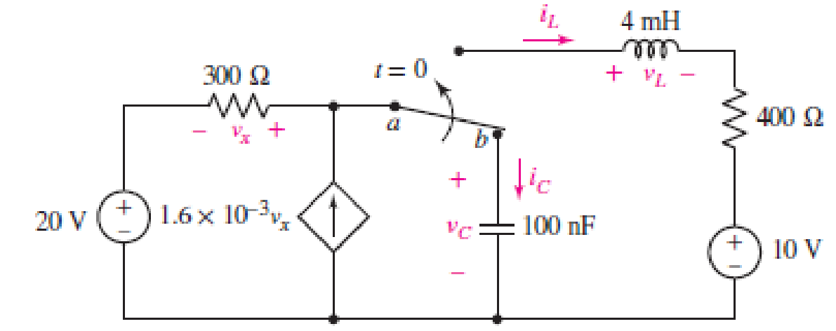
■ FIGURE 9.52
Expert Solution & Answer
Want to see the full answer?
Check out a sample textbook solution
Students have asked these similar questions
An initially charged capacitor has an initial voltage of Vo=53 Vand a capacitance ofC=175μFand it is connected to a resistor of resistance R=4.85kΩas shown in the figure below. The switch is closed at t=0. Determine the current running in the circuit one time constant after the switch is closed. Express your answer in units of mA using one decimal place.
9798
"For a practical inductor, the current leads the voltage by an angle of less than 90 degrees."
True
False
"By practice, an ideal capacitor does not model a practical capacitor quite accurately."
True
False
Switch
KC
xC
The circuit above has a switch that connects one capacitor and a resistor to a battery when
in position A, and connects that capacitor and resistor to a second capacitor and resistor when
in position B. Both capacitors have capacitance C when they are filled with nothing. We begin
this problem with both capacitors uncharged, but filled with a solid with dielectric constant x.
(a) The switch is set to position A at a time t = 0. After waiting a long time, what is the
charge on the capacitor? What is the energy stored in the capacitor.
(b) The switch is moved from position A to position B, connecting the charged capacitor to
the uncharged one. After a long time, what is the charge on each of the two capacitors?
Remember that charge is conserved.
(c) How much energy was lost to heat in this transfer of charge? Hint: You will not need to
compute an integral, nor do you need to know the amount of resistance in the circuit.
(d) The dielectric material is slowly pulled out of the…
Chapter 9 Solutions
Loose Leaf for Engineering Circuit Analysis Format: Loose-leaf
Ch. 9.1 - A parallel RLC circuit contains a 100 2 resistor...Ch. 9.2 - After being open for a long time, the switch in...Ch. 9.2 - Prob. 3PCh. 9.2 - Prob. 4PCh. 9.3 - (a) Choose R1 in the circuit of Fig. 9.14 so that...Ch. 9.4 - Prob. 6PCh. 9.5 - Prob. 7PCh. 9.5 - Prob. 8PCh. 9.6 - Let is = 10u(t) 20u(t) A in Fig. 9.31. Find (a)...Ch. 9.6 - Let vs = 10 + 20u(t) V in the circuit of Fig....
Ch. 9.7 - Alter the capacitor value and voltage source in...Ch. 9 - For a certain source-free parallel RLC circuit, R...Ch. 9 - Element values of 10 mF and 2 nH are employed in...Ch. 9 - If a parallel RLC circuit is constructed from...Ch. 9 - Prob. 4ECh. 9 - You go to construct the circuit in Exercise 1,...Ch. 9 - A parallel RLC circuit has inductance 2 mH and...Ch. 9 - Prob. 7ECh. 9 - A parallel RLC circuit has R = 1 k, L = 50 mH. and...Ch. 9 - Prob. 9ECh. 9 - Prob. 10ECh. 9 - The current flowing through a 5 resistor in a...Ch. 9 - For the circuit of Fig.9.40, obtain an expression...Ch. 9 - Consider the circuit depicted in Fig. 9.40. (a)...Ch. 9 - With regard to the circuit represented in Fig....Ch. 9 - (a) Assuming the passive sign convention, obtain...Ch. 9 - With regard to the circuit presented in Fig. 9.42,...Ch. 9 - Obtain expressions for the current i(t) and...Ch. 9 - FIGURE 9.43 Replace the 14 resistor in the...Ch. 9 - Design a complete source-free parallel RLC circuit...Ch. 9 - For the circuit represented by Fig. 9.44, the two...Ch. 9 - Prob. 21ECh. 9 - Prob. 22ECh. 9 - A critically damped parallel RLC circuit is...Ch. 9 - A source-free parallel RLC circuit has an initial...Ch. 9 - A critically damped parallel RLC circuit is...Ch. 9 - For the circuit of Fig. 9.45, is(t) = 30u(t) mA....Ch. 9 - Prob. 27ECh. 9 - The circuit of Fig. 9.44 is rebuilt such that the...Ch. 9 - Prob. 29ECh. 9 - Prob. 30ECh. 9 - The source-free circuit depicted in Fig. 9.1 is...Ch. 9 - (a) Graph the current i for the circuit described...Ch. 9 - Analyze the circuit described in Exercise 31 to...Ch. 9 - A source-free parallel RLC circuit has capacitance...Ch. 9 - Prob. 35ECh. 9 - Obtain an expression for vL(t), t 0, for the...Ch. 9 - For the circuit of Fig. 9.47, determine (a) the...Ch. 9 - (a) Design a parallel RLC circuit that provides a...Ch. 9 - The circuit depicted in Fig. 9.48 is just barely...Ch. 9 - When constructing the circuit of Fig. 9.48, you...Ch. 9 - The circuit of Fig. 9.22a is constructed with a...Ch. 9 - Prob. 42ECh. 9 - Prob. 43ECh. 9 - The simple three-element series RLC circuit of...Ch. 9 - Prob. 45ECh. 9 - Prob. 46ECh. 9 - Prob. 47ECh. 9 - With reference to the series RLC circuit of Fig....Ch. 9 - Obtain an expression for i1 as labeled in Fig....Ch. 9 - The circuit in Fig. 9.52 has the switch in...Ch. 9 - For the circuit in Fig. 9.52, determine the value...Ch. 9 - In the series circuit of Fig. 9.53, set R = 1 ....Ch. 9 - Evaluate the derivative of each current and...Ch. 9 - Consider the circuit depicted in Fig. 9.55. If...Ch. 9 - Prob. 55ECh. 9 - In the circuit shown in Fig. 9.56, (a) obtain an...Ch. 9 - Prob. 57ECh. 9 - For the circuit represented in Fig. 9.57, (a)...Ch. 9 - FIGURE 9.57 Replace the 1 resistor in Fig. 9.57...Ch. 9 - A circuit has an inductive load of 2 H, a...Ch. 9 - (a) Adjust the value of the 3 resistor in the...Ch. 9 - Determine expressions for vC(t) and iL(t) in Fig....Ch. 9 - The capacitor in the LC circuit in Fig. 9.60 has...Ch. 9 - Suppose that the switch in the circuit in Fig....Ch. 9 - The capacitor in the circuit of Fig. 9.63 is set...Ch. 9 - The physical behavior of automotive suspension...Ch. 9 - A lossless LC circuit can be used to provide...
Additional Engineering Textbook Solutions
Find more solutions based on key concepts
When travelers from the USA and Canada visit Europe, they encounter a different power distribution system. Wall...
Electric machinery fundamentals
A constant voltage of 10V is applied to a 50H inductance, as shown in Figure P3.51 Figure P3 51 The current in ...
Electrical Engineering: Principles & Applications (7th Edition)
How many coulombs do 93.8 1016 electrons represent?
Principles Of Electric Circuits
For the “tank” circuit in Fig. 14.79, find the resonant frequency.
Figure 14.79
For Probs. 14.39, 14.71, and 1...
Fundamentals of Electric Circuits
Three point charges of equal magnitude q, that will yield a zero net electric field at the origin.
Engineering Electromagnetics
Identify the type of input and output configuration for each diff-amp in Figure 18-35.
Electronics Fundamentals: Circuits, Devices & Applications
Knowledge Booster


Learn more about
Need a deep-dive on the concept behind this application? Look no further. Learn more about this topic, electrical-engineering and related others by exploring similar questions and additional content below.Similar questions
- #14 The "charge-holding" ability of a capacitor is called its capacitance. a True b Falsearrow_forwardThe capacitor is sufficiently discharged in the next circuit and the switch is closed at t=0. Answer the question. a) Capacitor current at t=0 and IR(current) b) t=infinity Find the capacitor current and voltage. c) After opening the switch, find the IR, IC. d) Time constant.arrow_forwardChoose the TRUE statement: a) A capacitor is rated according to its maximum allowable voltage and capacitance value. Increasing the distance between the plates of a capacitor would yield a higher O b) capacitance. O) Electrolytic capacitors are non-polarized. O d) The major reason for using electrolytic capacitors is that they have a very low d) capacitance but can handle very low voltages.arrow_forward
- The following figure represents an RC-Circuit with the switch. In Figure A, the capacitor is initially uncharged. In Figure B, the capacitor is initially fully charged. 1) Draw and label the current direction immediately after the switch is closed for each figure. 2) Consider Figure A. What is the voltage across the capacitor as t → 0? Explain. 3) Consider Figure B. Is the voltage across the resistor increasing, decreasing or staying the same as t → 0? Explain. A) B) R Carrow_forwardPlease help will upvote for sureFor the circuit below:a) What is the maximum current at any time in the circuit?b) Write Equation of capacitor voltage in any time and find the capacitor voltage at t=1msec, t=10msec, t=1sec and t=10sec?d) Draw the capacitor voltage and current signal versus time axis and sign four different time values in (c) on it?arrow_forward2. A capacitor having a capacitance of 2.0 µF consists of two metal elec- trodes separated by an insulating spacer made of crystalline silicon. Silicon is a semiconductor, having a conductivity of 1.6x10⁻³ S/m and dielectric constant of 11.7. The capacitor is placed in a series with a 12 volt battery in a closed loop circuit. When steady state is reached, what is the charge on the capacitor, and what is the current in the circuit?arrow_forward
- The initial capacitor voltage is 4 V. Switch S1 is closed at t = 0. The charge (in micro C) lost by the capacitor form t = 25 microS to t = 100 microS is:1) 6.992) 8.713) 5.554) 10Please show detailed steps and workarrow_forwardThe circuit shown consists of four capacitors, an ideal battery of emf &, a switch 'S' and an inductor of inductance L. The switch Sis kept open for a long time. Find the maximum current through the inductor after the switch 'S' is closed. 2C 4C C S 8 3C =8arrow_forward7. The voltage across a 22 u F capacitor is shown in Figure 9 below. 15 10 2 4 t(ms) Figure 9 (a) State the relationship between the voltage and the current of the capacitor. (b) Sketch the waveform for the current in the capacitor. (c) Determine the energy stored in the capacitor at t = 6 ms.arrow_forward
- A 15.5 kQ resistor and a capacitor are connected in series and then a 12.0 V potential difference is suddenly applied across them. The potential difference across the capacitor rises to 8.94 V in 1.64 us. (a) Calculate the time constant of the circuit. (b) Find the capacitance of the capacitor. (a) Number Units (b) Number.. eTextbook and Media Hint Save for Later Units Attempts: unlimited Submit Answerarrow_forward(c) For the circuit in Figure Q1(c), under DC condition: (i) Determine the voltage across the capacitor, Ve and the current flow through the inductor, IL. (ii) Determine the energy stored in the inductor, W1 and energy store in capacitor, W. 50 160µF + Vc - 5A 20 4mH Figure Q1(c) -W-arrow_forward5. Find the capacitor voltage in the network shown in figure. If the switch closes at t-0. Assume zero initial conditions. Also find the time constant, rise time, and settling time for the capacitor voltage 1=0 ww 1.802 0.79 Farrow_forward
arrow_back_ios
SEE MORE QUESTIONS
arrow_forward_ios
Recommended textbooks for you
 Introductory Circuit Analysis (13th Edition)Electrical EngineeringISBN:9780133923605Author:Robert L. BoylestadPublisher:PEARSON
 Delmar's Standard Textbook Of ElectricityElectrical EngineeringISBN:9781337900348Author:Stephen L. HermanPublisher:Cengage Learning
 Programmable Logic ControllersElectrical EngineeringISBN:9780073373843Author:Frank D. PetruzellaPublisher:McGraw-Hill Education
 Fundamentals of Electric CircuitsElectrical EngineeringISBN:9780078028229Author:Charles K Alexander, Matthew SadikuPublisher:McGraw-Hill Education
 Electric Circuits. (11th Edition)Electrical EngineeringISBN:9780134746968Author:James W. Nilsson, Susan RiedelPublisher:PEARSON
 Engineering ElectromagneticsElectrical EngineeringISBN:9780078028151Author:Hayt, William H. (william Hart), Jr, BUCK, John A.Publisher:Mcgraw-hill Education,
Introductory Circuit Analysis (13th Edition)
Electrical Engineering
ISBN:9780133923605
Author:Robert L. Boylestad
Publisher:PEARSON
Delmar's Standard Textbook Of Electricity
Electrical Engineering
ISBN:9781337900348
Author:Stephen L. Herman
Publisher:Cengage Learning
Programmable Logic Controllers
Electrical Engineering
ISBN:9780073373843
Author:Frank D. Petruzella
Publisher:McGraw-Hill Education
Fundamentals of Electric Circuits
Electrical Engineering
ISBN:9780078028229
Author:Charles K Alexander, Matthew Sadiku
Publisher:McGraw-Hill Education
Electric Circuits. (11th Edition)
Electrical Engineering
ISBN:9780134746968
Author:James W. Nilsson, Susan Riedel
Publisher:PEARSON
Engineering Electromagnetics
Electrical Engineering
ISBN:9780078028151
Author:Hayt, William H. (william Hart), Jr, BUCK, John A.
Publisher:Mcgraw-hill Education,
Capacitors Explained - The basics how capacitors work working principle; Author: The Engineering Mindset;https://www.youtube.com/watch?v=X4EUwTwZ110;License: Standard YouTube License, CC-BY