
Loose Leaf for Engineering Circuit Analysis Format: Loose-leaf
9th Edition
ISBN: 9781259989452
Author: Hayt
Publisher: Mcgraw Hill Publishers
expand_more
expand_more
format_list_bulleted
Concept explainers
Videos
Textbook Question
Chapter 9, Problem 32E
(a) Graph the current i for the circuit described in Exercise 31 for resistor values 1.5 kΩ, 15 kΩ, and 150 kΩ. Make three separate graphs, and be sure to extend the corresponding time axis to observe the settling time in each case. (b) Determine the corresponding settling times.
31. The source-free circuit depicted in Fig. 9.1 is constructed using a 10 mH inductor, a 1 mF capacitor, and a 1.5 kΩ resistor. (a) Calculate α, ωd, and ω0. (b) Write the equation which describes the current i for t > 0. (c) Determine the maximum value of i, and the time at which it occurs, if the inductor initially stores no energy and v(0−) = 9 V.
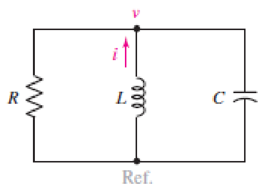
■ FIGURE 9.1 The source-free parallel RLC circuit.
Expert Solution & Answer
Want to see the full answer?
Check out a sample textbook solution
Students have asked these similar questions
I Review | Constants
In the circuit shown in the following figure(Figure 1) the
capacitor has capacitance 17 uF and is initially
uncharged. The resistor Ro has resistance 11N. An emf
of 91.0 V is added in series with the capacitor and the
resistor. The emf is placed between the capacitor and the
switch, with the positive terminal of the emf adjacent to
the capacitor. The small circuit is not connected in any
way to the large one. The wire of the small circuit has a
resistance of 1.0 N/m and contains 30 loops. The large
Part A
The switch is closed at t = 0. When the current in the large circuit is 3.10 A , what is the magnitude of the induced current in
the small circuit?
Express your answer with the appropriate units.
circuit is a rectangle 2.0 m by 4.0 m, while the small one
has dimensions a = 13.0 cm and b = 23.0 cm. The
distance c is 4.0 cm. (The figure is not drawn to scale.)
Both circuits are held stationary. Assume that only the
wire nearest the small circuit produces an…
For the circuit in Figure 3 the switch is in the left position
for several minutes:
(a) Find the Initlal voltage, V, on the capacitor just
before the switch is flipped
(b) Find an expression v(t) that describes the voltage
across the 20 N resistor after the switch has been
Figure 3
U 09
flipped to the right
NOTE: Remember what we said in class: use a Circuit-Specific
Equation to get a value you know. Then solve for whatever else
the problem asks for
+50 µF 380 0 20 2
A voltage of .... appears between the terminals of a combination of a 100 mF capacitor and a 12 oms resistor in parallel. Calculate the power absorbed by the parallel combination.
Note: I leave the image of the exercises in Spanish, but it is easy to understand.
Also in the other image is the correct final answer, for checking.
IMPORTANT:Please, preferably the procedure should be digital, not on paper.This way I understand better.I would appreciate it very much!
Chapter 9 Solutions
Loose Leaf for Engineering Circuit Analysis Format: Loose-leaf
Ch. 9.1 - A parallel RLC circuit contains a 100 2 resistor...Ch. 9.2 - After being open for a long time, the switch in...Ch. 9.2 - Prob. 3PCh. 9.2 - Prob. 4PCh. 9.3 - (a) Choose R1 in the circuit of Fig. 9.14 so that...Ch. 9.4 - Prob. 6PCh. 9.5 - Prob. 7PCh. 9.5 - Prob. 8PCh. 9.6 - Let is = 10u(t) 20u(t) A in Fig. 9.31. Find (a)...Ch. 9.6 - Let vs = 10 + 20u(t) V in the circuit of Fig....
Ch. 9.7 - Alter the capacitor value and voltage source in...Ch. 9 - For a certain source-free parallel RLC circuit, R...Ch. 9 - Element values of 10 mF and 2 nH are employed in...Ch. 9 - If a parallel RLC circuit is constructed from...Ch. 9 - Prob. 4ECh. 9 - You go to construct the circuit in Exercise 1,...Ch. 9 - A parallel RLC circuit has inductance 2 mH and...Ch. 9 - Prob. 7ECh. 9 - A parallel RLC circuit has R = 1 k, L = 50 mH. and...Ch. 9 - Prob. 9ECh. 9 - Prob. 10ECh. 9 - The current flowing through a 5 resistor in a...Ch. 9 - For the circuit of Fig.9.40, obtain an expression...Ch. 9 - Consider the circuit depicted in Fig. 9.40. (a)...Ch. 9 - With regard to the circuit represented in Fig....Ch. 9 - (a) Assuming the passive sign convention, obtain...Ch. 9 - With regard to the circuit presented in Fig. 9.42,...Ch. 9 - Obtain expressions for the current i(t) and...Ch. 9 - FIGURE 9.43 Replace the 14 resistor in the...Ch. 9 - Design a complete source-free parallel RLC circuit...Ch. 9 - For the circuit represented by Fig. 9.44, the two...Ch. 9 - Prob. 21ECh. 9 - Prob. 22ECh. 9 - A critically damped parallel RLC circuit is...Ch. 9 - A source-free parallel RLC circuit has an initial...Ch. 9 - A critically damped parallel RLC circuit is...Ch. 9 - For the circuit of Fig. 9.45, is(t) = 30u(t) mA....Ch. 9 - Prob. 27ECh. 9 - The circuit of Fig. 9.44 is rebuilt such that the...Ch. 9 - Prob. 29ECh. 9 - Prob. 30ECh. 9 - The source-free circuit depicted in Fig. 9.1 is...Ch. 9 - (a) Graph the current i for the circuit described...Ch. 9 - Analyze the circuit described in Exercise 31 to...Ch. 9 - A source-free parallel RLC circuit has capacitance...Ch. 9 - Prob. 35ECh. 9 - Obtain an expression for vL(t), t 0, for the...Ch. 9 - For the circuit of Fig. 9.47, determine (a) the...Ch. 9 - (a) Design a parallel RLC circuit that provides a...Ch. 9 - The circuit depicted in Fig. 9.48 is just barely...Ch. 9 - When constructing the circuit of Fig. 9.48, you...Ch. 9 - The circuit of Fig. 9.22a is constructed with a...Ch. 9 - Prob. 42ECh. 9 - Prob. 43ECh. 9 - The simple three-element series RLC circuit of...Ch. 9 - Prob. 45ECh. 9 - Prob. 46ECh. 9 - Prob. 47ECh. 9 - With reference to the series RLC circuit of Fig....Ch. 9 - Obtain an expression for i1 as labeled in Fig....Ch. 9 - The circuit in Fig. 9.52 has the switch in...Ch. 9 - For the circuit in Fig. 9.52, determine the value...Ch. 9 - In the series circuit of Fig. 9.53, set R = 1 ....Ch. 9 - Evaluate the derivative of each current and...Ch. 9 - Consider the circuit depicted in Fig. 9.55. If...Ch. 9 - Prob. 55ECh. 9 - In the circuit shown in Fig. 9.56, (a) obtain an...Ch. 9 - Prob. 57ECh. 9 - For the circuit represented in Fig. 9.57, (a)...Ch. 9 - FIGURE 9.57 Replace the 1 resistor in Fig. 9.57...Ch. 9 - A circuit has an inductive load of 2 H, a...Ch. 9 - (a) Adjust the value of the 3 resistor in the...Ch. 9 - Determine expressions for vC(t) and iL(t) in Fig....Ch. 9 - The capacitor in the LC circuit in Fig. 9.60 has...Ch. 9 - Suppose that the switch in the circuit in Fig....Ch. 9 - The capacitor in the circuit of Fig. 9.63 is set...Ch. 9 - The physical behavior of automotive suspension...Ch. 9 - A lossless LC circuit can be used to provide...
Knowledge Booster


Learn more about
Need a deep-dive on the concept behind this application? Look no further. Learn more about this topic, electrical-engineering and related others by exploring similar questions and additional content below.Similar questions
- The figure below shows a simple RC circuit with a 3.10-μF capacitor, a 3.60-MQ resistor, a 9.00-V emf, and a switch. What are the following exactly 8.50 s after the switch is closed? (a) the charge on the capacitor μC (b) the current in the resistor μA R (c) the rate at which the capacitor is storing energy μW (d) the rate at which the battery is delivering energy μWarrow_forwardPlease help will upvote for sureFor the circuit below:a) What is the maximum current at any time in the circuit?b) Write Equation of capacitor voltage in any time and find the capacitor voltage at t=1msec, t=10msec, t=1sec and t=10sec?d) Draw the capacitor voltage and current signal versus time axis and sign four different time values in (c) on it?arrow_forwardA voltage of .... appears between the terminals of a combination of a 100 mF capacitor and a 12 oms resistor in parallel. Calculate the power absorbed by the parallel combination. Note: I leave the image of the exercises in Spanish, but it is easy to understand. Also in the other image is the correct final answer, for checking.arrow_forward
- The R-L Circuit: An inductor with an inductance of 2.50 H and a resistance of 7.00 n is connected to the terminals ofa battery with an emf of 6.00 V and an internal resistance of 1.00 n. What is the rate ofincrease of current at the instant when the current is 0.500 A? A) 0.8 A/s B) 0.6 A/s C) 0.4 A/s D) zero E) None of the above.arrow_forward2. A capacitor having a capacitance of 2.0 µF consists of two metal elec- trodes separated by an insulating spacer made of crystalline silicon. Silicon is a semiconductor, having a conductivity of 1.6x10⁻³ S/m and dielectric constant of 11.7. The capacitor is placed in a series with a 12 volt battery in a closed loop circuit. When steady state is reached, what is the charge on the capacitor, and what is the current in the circuit?arrow_forwardA capacitor C with 1 mF is charged by a constant voltage source (U). Source and capacitor are connected by a resistor R with 10 ko. To discharge the capacitor the source is replaced by a short. U R 1 R charging discharging The voltage source is replaced by a constant current source with an output of 1 mA. Please draw the voltage at the capacitor qualitatively over the time.arrow_forward
- 1. Find the voltages across the following components (a and b) after 1 second. The Capacitor is initially charged at 10V while the voltage source is 1V. Resistor R is 103 ohm while capacitor C is 1mF. a. Capacitor C b. Resistor R c. What is the best 1st order DE Method applicable to this problem?arrow_forwardIn the above circuit, the switch is open for a long time.i)The switch closes for 50 us. What is the current through the inductor? Also, what is the voltage at the output with respect to ground just before the switch open?ii) The switch closes. What is the maximum current the inductor will see?arrow_forwardA capacitor is charged to a potential of 12.0V and is then connected to a voltmeter having an internal resistance of 3.20MQ. After a time of 2.00s, the voltmeter reads 2.0V. A) what is the capacitance of the circuit? B)What is the time constant of the circuit c A capacitor is charged to a potential of 12.0 V and is then connected to a voltmeter having an internal resistance of 3.20 MS. After a time of 2.00 s, the voltmeter reads 2.0 V.arrow_forward
- There is no energy stored in the circuit at the timethe current source is energized.1. a) Find Ia and Ib.2. b) Find ia and ib.3. c) Find Va, Vb, and Ic.4. d) Find va, vb, and vc.5. e) Assume a capacitor will break down whenever its terminal voltage is 1000 V. How long after the current source turns on willone of the capacitors break down?arrow_forwardBasic Electrical Engineering: Inductance and Capacitance You are an electrician working in an industrial plant. You discover the problem with a certain machine is a defective capacitor. The capacitor is connected to a 240-V AC circuit. The information on the capacitor reveals that it has a capacitance value of 10 µF and a voltage rating of 240 V AC. The only 10-µF capacitor in the storeroom is marked with a voltage rating 350 VDC. Can this capacitor be used to replace the defective capacitor? Explain your answer.arrow_forward- Refer to the figure and generate a mathematical model for Capacitor Given the relationship i(t) = Cdv/dt Solve and derive an equation for the voltage relation v(t) Inductor Given the relationship v(t) = Ldi/dt Solve and derive an equation for the voltage relation i(t)Solve and derive an equation for the voltage relation v(t) Inductance i(t) di(t) dt v (t) = Lº L v (t) = Capacitance i(t) (116) C i(r) dr + v (0)arrow_forward
arrow_back_ios
SEE MORE QUESTIONS
arrow_forward_ios
Recommended textbooks for you
 Introductory Circuit Analysis (13th Edition)Electrical EngineeringISBN:9780133923605Author:Robert L. BoylestadPublisher:PEARSON
 Delmar's Standard Textbook Of ElectricityElectrical EngineeringISBN:9781337900348Author:Stephen L. HermanPublisher:Cengage Learning
 Programmable Logic ControllersElectrical EngineeringISBN:9780073373843Author:Frank D. PetruzellaPublisher:McGraw-Hill Education
 Fundamentals of Electric CircuitsElectrical EngineeringISBN:9780078028229Author:Charles K Alexander, Matthew SadikuPublisher:McGraw-Hill Education
 Electric Circuits. (11th Edition)Electrical EngineeringISBN:9780134746968Author:James W. Nilsson, Susan RiedelPublisher:PEARSON
 Engineering ElectromagneticsElectrical EngineeringISBN:9780078028151Author:Hayt, William H. (william Hart), Jr, BUCK, John A.Publisher:Mcgraw-hill Education,
Introductory Circuit Analysis (13th Edition)
Electrical Engineering
ISBN:9780133923605
Author:Robert L. Boylestad
Publisher:PEARSON
Delmar's Standard Textbook Of Electricity
Electrical Engineering
ISBN:9781337900348
Author:Stephen L. Herman
Publisher:Cengage Learning
Programmable Logic Controllers
Electrical Engineering
ISBN:9780073373843
Author:Frank D. Petruzella
Publisher:McGraw-Hill Education
Fundamentals of Electric Circuits
Electrical Engineering
ISBN:9780078028229
Author:Charles K Alexander, Matthew Sadiku
Publisher:McGraw-Hill Education
Electric Circuits. (11th Edition)
Electrical Engineering
ISBN:9780134746968
Author:James W. Nilsson, Susan Riedel
Publisher:PEARSON
Engineering Electromagnetics
Electrical Engineering
ISBN:9780078028151
Author:Hayt, William H. (william Hart), Jr, BUCK, John A.
Publisher:Mcgraw-hill Education,
ENA 9.2(1)(En)(Alex) Sinusoids & Phasors - Explanation with Example 9.1 ,9.2 & PP 9.2; Author: Electrical Engineering Academy;https://www.youtube.com/watch?v=vX_LLNl-ZpU;License: Standard YouTube License, CC-BY
Electrical Engineering: Ch 10 Alternating Voltages & Phasors (8 of 82) What is a Phasor?; Author: Michel van Biezen;https://www.youtube.com/watch?v=2I1tF3ixNg0;License: Standard Youtube License