
Shigley's Mechanical Engineering Design (McGraw-Hill Series in Mechanical Engineering)
10th Edition
ISBN: 9780073398204
Author: Richard G Budynas, Keith J Nisbett
Publisher: McGraw-Hill Education
expand_more
expand_more
format_list_bulleted
Concept explainers
Videos
Textbook Question
Chapter 6, Problem 25P
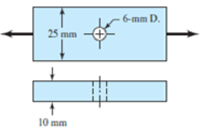
The cold-drawn AISI KUO steel bar shown in the figure is subjected to a completely reversed axial load fluctuating between 28 kN in compression to 28 kN in tension. Estimate the fatigue factor of safety based on achieving infinite life and the yielding factor of safety. If infinite life is not predicted, estimate the number of cycles to failure.
Problem 6-25
Expert Solution & Answer
Want to see the full answer?
Check out a sample textbook solution
Students have asked these similar questions
6-25 The cold-drawn AISI 1040 steel bar shown in the figure
reversed axial load fluctuating between 28 kN in compression to 28 kN in tension.
Estimate the fatigue factor of safety based on achieving infinite life and the yielding
factor of safety. If infinite life is not predicted, estimate the number of cycles to failure.
6-mm D.
25 mm
Problem 6-25
10 mm
The cold-drawn AISI 1040 steel bar shown in the figure is subjected to a completely reversed
axial load fluctuating between 15 kN in compression to 15 kN in tension. Estimate the fatigue
factor of safety based on achieving infinite life, and the yielding factor of safety. If infinite life is
not predicted, estimate the number of cycles to failure.
6 mm D.
25 mm
10 mm
Required information
The cold-drawn AISI 1040 steel bar shown in the figure is subjected to an axial load that fluctuates from 8 kN to 30 kN.
Use the Modified Goodman criterion and estimate the fatigue factor of safety based on achieving infinite life and the
yielding factor of safety.
25 mm
10mm
-6-mm D.
What is the number of cycles to failure for this part?
The number of cycles is 120000
Chapter 6 Solutions
Shigley's Mechanical Engineering Design (McGraw-Hill Series in Mechanical Engineering)
Ch. 6 - A 10-mm steel drill rod was heat-treated and...Ch. 6 - Prob. 2PCh. 6 - A steel rotating-beam test specimen has an...Ch. 6 - A steel rotating-beam test specimen has an...Ch. 6 - A steel rotating-beam test specimen has an...Ch. 6 - Repeat Prob. 6-5 with the specimen having an...Ch. 6 - A steel rotating-beam test specimen has an...Ch. 6 - Derive Eq. (6-17). Rearrange the equation to solve...Ch. 6 - For the interval 103 N 106 cycles, develop an...Ch. 6 - Estimate the endurance strength of a...
Ch. 6 - Two steels are being considered for manufacture of...Ch. 6 - A 1-in-diamctcr solid round bar has a groove...Ch. 6 - A solid square rod is cantilevered at one end. The...Ch. 6 - A rectangular bar is cut from an AISI 1020...Ch. 6 - A solid round bar with diameter of 2 in has a...Ch. 6 - The rotating shaft shown in the figure is machined...Ch. 6 - The shaft shown in the figure is machined from...Ch. 6 - Solve Prob. 6-17 except with forces F1 = 1200 lbf...Ch. 6 - Bearing reactions R1 and R2 are exerted on the...Ch. 6 - A bar of steel has the minimum properties Se = 40...Ch. 6 - Repeat Prob. 6-20 but with a steady torsional...Ch. 6 - Repeat Prob. 6-20 but with a steady torsional...Ch. 6 - Repeat Prob. 6-20 but with an alternating...Ch. 6 - A bar of steel has the minimum properties Se = 40...Ch. 6 - The cold-drawn AISI KUO steel bar shown in the...Ch. 6 - Repeat Prob. 6-25 for a load that fluctuates from...Ch. 6 - An M14 2 hex-head bolt with a nut is used to...Ch. 6 - The figure shows a formed round-wire cantilever...Ch. 6 - The figure is a drawing of a 4- by 20-mm latching...Ch. 6 - The figure shows the free-body diagram of a...Ch. 6 - Solve Prob. 6-30 except let w1 = 2.5 in. w2 = l.5...Ch. 6 - For the part in Prob. 630, recommend a fillet...Ch. 6 - Prob. 33PCh. 6 - Prob. 34PCh. 6 - A part is loaded with a combination of bending,...Ch. 6 - Repeat the requirements of Prob. 6-35 with the...Ch. 6 - 6-37 to 6-46For the problem specified in the build...Ch. 6 - 6-37 to 6-46For the problem specified in the build...Ch. 6 - 637 to 646 For the problem specified in the table,...Ch. 6 - For the problem specified in the table, build upon...Ch. 6 - 6-37 to 6-46 For the problem specified in the...Ch. 6 - 6-37 to 6-46 For the problem specified in the...Ch. 6 - 6-37 to 6-46 For the problem specified in the...Ch. 6 - Problem Number Original Problem, Page Number 637...Ch. 6 - 6-37 to 6-46 For the problem specified in the...Ch. 6 - 6-37 to 6-46 For the problem specified in the...Ch. 6 - 6-47 to 6-50 For the problem specified in the...Ch. 6 - 6-47 to 6-50 For the problem specified in the...Ch. 6 - Prob. 49PCh. 6 - Prob. 50PCh. 6 - 6-51 to 6-53 For the problem specified in the...Ch. 6 - 6-51 to 6-53 For the problem specified in the...Ch. 6 - 6-51 to 6-53 For the problem specified in the...Ch. 6 - Solve Prob. 6-17 except include a steady torque of...Ch. 6 - Solve Prob. 618 except include a steady torque of...Ch. 6 - In the figure shown, shaft A, made of AISI 1020...Ch. 6 - A schematic of a clutch-testing machine is shown....Ch. 6 - For the clutch of Prob. 657, the external load P...Ch. 6 - A flat leaf spring has fluctuating stress of max =...Ch. 6 - A rotating-beam specimen with an endurance limit...Ch. 6 - A machine part will be cycled at 350 MPa for 5...Ch. 6 - The material properties of a machine part are Sut...Ch. 6 - Repeat Prob. 662 using the Goodman criterion....
Knowledge Booster


Learn more about
Need a deep-dive on the concept behind this application? Look no further. Learn more about this topic, mechanical-engineering and related others by exploring similar questions and additional content below.Similar questions
- Three round, copper alloy bars having the same length L but different shapes are shown, in the figure. The first bar has a diameter d over its entire length, the second has a diameter d over one-fifth of its length, and the third has a diameter d over one-fifteenth of its length. Elsewhere, the second and third bars have a diameter Id. All three bars are subjected to the same axial load P. Use the following numerical data: P = 1400 kN, L = 5m,d= 80 mm, E= 110 GPa. and v = 0.33. (a) Find the change in length of each bar. (b) Find the change in volume of each bar.arrow_forwardA crank arm consists of a solid segment of length bxand diameter rf, a segment of length bltand a segment of length byas shown in the figure. Two loads P act as shown: one parallel to — vand another parallel to —y. Each load P equals 1.2 kN. The crankshaft dimensions are A] = 75 mm, fr> = 125 mm, and b3= 35 mm. The diameter of the upper shaft isd = 22 mm, (a) Determine the maximum tensile, compressive, and shear stresses at point A, which is located on the surface of the shaft at the z axis. (b) Determine the maximum tensile, compressive, and shear stresses at point B, which is located on the surface of the shaft at the y axisarrow_forwardRepeat Problem 2.3-18, but assume that the bar is made of copper alloy. Calculate the displacements SBand Scif P = 50 kips, L = 5 ft = 3/5 in., b1= 2.75 in., b2= 3 in., and E = 16,000 ksi.arrow_forward
- Repeat Problem 2.3-4, but now include the weight of the bar. Sec Table 1.1 in Appendix I for the weight density of steel.arrow_forwardThe figure shows a shaft mounted in bearings at A and D and having pulleys at B and C. The forces shown acting on the pulley surfaces represent the belt tensions. The shaft is to be made of AISI 1035 CD steel. The shaft is rotating at speed of 1000 rpm. Find the minimum factor of safety for fatigue based on infinite life. If the life is not infinite, estimate the number of cycles. Be sure to check for yielding. Take shaft diameter to be 1.5 inches.arrow_forwardThe cold-drawn AISI 1040 Q&T at 205 ◦C steel bar shown in the figure is subjected to a completely reversed axial load fluctuating between 28 kN in compression to 28 kN in tension. Estimate the fatigue factor of safety based on achieving infinite life, and the yielding factor of safety for the following cases. If infinite life is not predicted, estimate the number of cycles to failure.a) for the part given in Fig 2(a) and b) for the part given in Fig. 2 (b) using the same dimensions (W=25mm, r=3mm, the thickness of 10 mm)arrow_forward
- The cold-drawn AISI 1040 steel bar shown in the figure is subjected to an axial load fluctuating between 0kN and 28kN. Estimate the fatigue factor of safety based on achieving infinite life using modified Goodman criterion and the yielding factor of safety. If infinite life is not predicted, estimate the number of cycles to failure.arrow_forwardThe figure below shows a boat propeller mounted on a drive shaft with a 7 mm diameter (d) cylindrical drive pin inserted through the hub and the shaft. The drive shaft diameter, D, inside the hub is 69 mm. The pin is made from AISI 1020 cold rolled steel, which has a yield stress of 427 MPa and an ultimate stress of 621 MPa. If the drive pin is subjected to an overload (e.g. strikes a log), calculate the torque (Nm) required to shear the pin. Note: Assume that the max shear stress of the pin material is approximately equal 82% of the ultimate tensile stress. Do not include units in your answer. Pin F Hub Drive pin Shaft Drive shaft F Shear planes Hub Answer:arrow_forwardThe hydraulic cylinder shown in the figure has a 2-in bore and is to operate at a pressure of 1500 psi. With the clevis mount shown, the piston rod should be sized as a column with both ends rounded for any plane of buckling. The rod is to be made of forged AISI 1030 steel without further heat treatment resulting in yield strength of 37.5 kpsi, and Young's modulus of 30 mpsi. Problem 4-131 (a) Use a design factor na = 2.5 and select a preferred size for the rod diameter if the column length is 50 in. (b) Repeat part (a) but for a column length of 16 in. (c) What factor of safety actually results for each of the cases above?arrow_forward
- 6-28 The figure shows a formed round-wire cantilever spring subjected to a varying force. The hardness tests made on 50 springs gave a minimum hardness of 400 Brinell. It is apparent from the mounting details that there is no stress concentration. A visual inspection of the springs indicates that the surface finish corresponds closely to a hot- rolled finish. Ignore curvature effects on the bending stress. What number of applica- tions is likely to cause failure? Solve using: (a) Goodman criterion. (b) Gerber criterion. = 40 lbf max 12 in- = 20 lbf min Problem 6-28arrow_forward6-10 A rotating shaft of 25-mm diameter is simply supported by bearing reaction forces R, and R2. The shaft is loaded with a transverse load of 13 kN as shown in the figure. The shaft is made from AISI 1045 hot-rolled steel. The surface has been machined. Determine (a) the minimum static factor of safety based on yielding. (b) the endurance limit, adjusted as necessary with Marin factors. (c) the minimum fatigue factor of safety based on achieving infinite life. (d) If the fatigue factor of safety is less than 1 (hint: it should be for this problem), then estimate the life of the part in number of rotations.arrow_forward8-68 Engineering Design + 40 1 plem 8-68 70 millimeters. 40 A bolted lap joint using ISO class 5.8 bolts and members made of cold-drawn SAE 1040 steel is shown in the figure. Assume the bolt threads do not extend into the joint. Find the tensile shear load F that can be applied to this connection to provide a minimum factor of safety of 2.5 for the fol- lowing failure modes: shear of bolts, bearing on bolts, bearing on members, and tension of members. 20 M20x2.5 20arrow_forward
arrow_back_ios
SEE MORE QUESTIONS
arrow_forward_ios
Recommended textbooks for you
 Mechanics of Materials (MindTap Course List)Mechanical EngineeringISBN:9781337093347Author:Barry J. Goodno, James M. GerePublisher:Cengage Learning
Mechanics of Materials (MindTap Course List)
Mechanical Engineering
ISBN:9781337093347
Author:Barry J. Goodno, James M. Gere
Publisher:Cengage Learning
Everything About COMBINED LOADING in 10 Minutes! Mechanics of Materials; Author: Less Boring Lectures;https://www.youtube.com/watch?v=N-PlI900hSg;License: Standard youtube license