
Concept explainers
Videos
The two possible situations that will happen for the given conditions.
The diode current and terminal voltage across diode for two situations.
Answer to Problem 4.1P
The value of diode current and diode terminal voltage is:
For situation 1:
VD = 1.5 V
iD = 0 A
For situation 2:
Explanation of Solution
Given:
Thevenin equivalent of AA Flashlight cell with:
Thevenin voltage (Vth) = 1.5 V
Thevenin resistance (Rth) = 1 Ω
Positive side of battery is connected to the cathode of the ideal diode.
Calculation:
The two possible situations can be:
Situation 1: Cathode terminal of the diode is connected to the positive terminal of the battery.
Situation 2: Anode terminal of the diode is connected to the positive terminal of the battery.
Case 1:
When the cathode is connected to the positive terminal of battery.
The Thevenin equivalent circuit with diode connected as given can be drawn as:
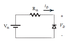
The diode is operating in a reversed biased region as the positive side of the battery is connected to the cathode terminal of diode.
Hence, the ideal diode will behave as an open circuit.
So,
Terminal voltage can be calculated by applying mesh law in the circuit:
By putting the given values and from equation (1):
Case 2:
When anode terminal of the diode is connected to the positive terminal of battery.
The Thevenin equivalent circuit with diode connected as given can be drawn as:
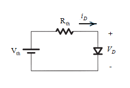
The diode is operating in forward biased region as the positive side of the battery is connected to the anode terminal of diode.
As it is ideal diode, the cut-in voltage across it will be 0.
Hence,
Current can be calculated by applying mesh law in the circuit:
By putting the given values and from equation (2):
Want to see more full solutions like this?
Chapter 4 Solutions
Microelectronic Circuits (The Oxford Series in Electrical and Computer Engineering) 7th edition


- How is a solid-state diode tested? Explain.arrow_forwardConsider the following diode circuit. 1kQ Vs 10 Vs VD t(ns) 10 -5 i. Calculate the current at t=0* in the circuit. ii. Calculate lş and IR when the diode is switched off at t=10 ns. Assume Von=0.7 V. i. Write the type of capacitances in a diode.arrow_forwardQuestion 1: In the circuit shown below, the output (Vo = 10V Max.) Unipolar. The frequency of Primary is 60 Hz. The diodes are Silicon with VD = 0.7V. a. Sketch the output without a Capacitor. b. Determine Voc without a Capacitor. c. Sketch Vs (at the Secondary). d. Determine Voc with a Capacitor of 10 uF across RL. e. Determine the RMS Value of Vp (at the Primary). f. PIV (Peak Inverse Voltage). 10:1 Output C. 22 k1 All diodes are IN4001. | 00000arrow_forward
- 4. Assume the Blue LED has a forward turn on voltage of 4 V and exhibits ideal diode behavior. For the circuit below, sketch the voltage across the diode and the voltage across the resistor (versus time) for the following Vin values. On your waveforms, indicate the time periods when the LED is on. a. Vin= 3 sin(2π *60t) V b. Vin = 5 sin(2π *60t) V Blue LED # Vin 1k R2arrow_forwardHow do I calculate the dynamic resistance of a zener diode with the following set of values given please? The circuit in figure is the circuit in question I am trying to solve this for please. Vin(DC) = 10V vin(ac) = 0.05sin(wt) Vz(voltage of diode) = 4.5V R1 = 1000 ohmsarrow_forwardA silicon diode is in parallel with a germanium diode and is connected to a load resistor having a value of 20 kQ and a forward supply voltage of 10 V. What is the approximate voltage across the silicon diode? * A. 10 V B. 1.0 V C. 0.7 V D. 0.3 Varrow_forward
- In the circuit given in the figure, find the current passing through the diode in mA since R1 = 4.95Kohm, R2 = 2.50Kohm, R3 = 1.69Kohm, R4 = 5.44Kohm, VCC = 13.00V and the diode is silicon?arrow_forward3: Using silicon diode design a clamper that will produce output V,-20Sin wt+10 (v) when the input voltage is Vo=20Sin wt-10 (V).Draw the circuit diagram and the input and output signals. 4:The 6-V zener diode has a maximum rated power dissipated of 690 mw.Its reveres current must be at least 3mA to keep it in breakdown. Find a suitable value for Rs if V; can vary from 9v to 12v and Ri. can vary from 5000 to 1.2KO.arrow_forwardConsider the diode circuit below, with both diodes having 0.7 V across them when they conduct. V(1) = 10sinwt V (AC)V(2) = 4 V (DC)R(1) = R (2) = 1.3 k(ohm) Over a full cycle of the AC input: 1. Calculate the maximum current through diode 1 (D1). Explain and show all steps. 2. Find the voltage across each resistor. Explain and show all steps. 3. Sketch the current waveform across diode 2 (D2). Label all important points. Explain and show all steps.arrow_forward
- Find the voltages at V1 and V2. Consider as a practical diode. (Show Complete Solution)arrow_forwardUsing the ideal diode model, find the output voltage for the input voltage of the following circuit and graph it in detail. (a) (b) R₁ D₁ www ww R3 D2 (a) R₁ D₁ www + + D2 R2 vo Vo R₂ (b)arrow_forwardWhat is an ideal diode? The ideal diode acts as an open circuit for forward currents (with voltage greater than the diode's forward voltage) and as a short circuit with reverse voltage applied The ideal diode acts as a short circuit regardless of forward voltage or reverse voltage applied The ideal diode acts as a short circuit for forward currents (with voltage greater than the diode's forward voltage) and as an open circuit with reverse voltage applied The ideal diode acts as an open circuit regardless of forward voltage or reverse voltage appliedarrow_forward
