
Videos
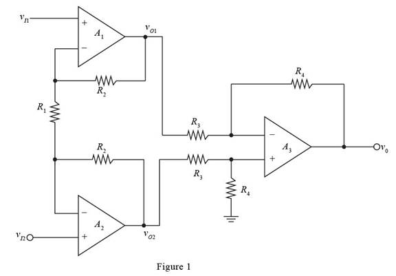
All parameters associated with the instrumentation amplifier in Figure 9.26are the same as given in Exercise Ex 9.8, except that resistor R3 , which isconnected to the inverting terminal of A3, is R3=30 kΩ±5% . Determinethe maximum common-mode gain.
The value of maximum common mode gain.
Answer to Problem 9.72P
The maximum value of the voltage gain is 0.0395 .
Explanation of Solution
Calculation:
The given diagram is shown in Figure 1
Mark the voltages and current and redraw the circuit.
The required diagram is shown in Figure 2
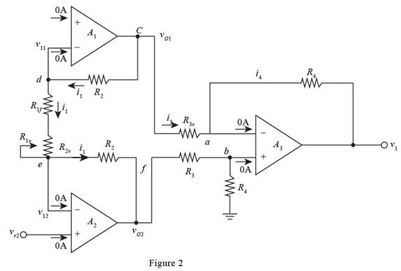
The expression for the voltage vb by voltage division rule is given by,
vb=R4vO2R3+R4
The expression for the current at the node va is given by,
va=vb
Substitute R4vO2R3+R4 for vb in the above equation.
va=R4vO2R3+R4
Apply KCL at the node va .
vO1−vaR3x=va−vOR4vO=(−R4R3x)vO1+(1+R4R3x)va
Substitute R4vO2R3+R4 for va in the above equation.
vO=(−R4R3x)vO1+(1+R4R3x)R4vO2R3+R4 ........ (1)
The expression for the value of the current i1 is given by,
i1=vI1−vI2R1
The expression for the voltage vO1 is given by,
vO1−vI1=i1R2
Substitute vI1−vI2R1 for i1 in the above equation.
vO1=vI1+(vI1−vI2R1)R2
The expression for the voltage vO2 is given by,
vO2=vI2−i1R2
Substitute vI1−vI2R1 for i1 in the above equation.
vO2=vI2−(vI1−vI2R1)R2
Substitute vI1+(vI1−vI2R1)R2 for vO1 and vI2−(vI1−vI2R1)R2 for vO2 in equation (1)
vO=(−R4R3x)(vI1+(vI1−vI2R1)R2)+(1+R4R3x)R4R3+R4(vI2−(vI1−vI2R1)R2)=(vI1−vI2R1)R2[(−R4R3x)−(1+R4R3x)(1+R4R3+R4)]−vI1(R4R3x)+vI2(1+R4R3x)(R4R3+R4) ........ (2)
The expression for the common mode voltage is given by,
vcm=vI1+vI22
The expression for the differential voltage is given by,
vd=vI2−vI1
The expression for the voltage vI2 is given by,
vI2=vcm+vd2
The expression for the voltage vI1 is given by,
vI1=vcm−vd2
Substitute vd for vI2−vI1 , vcm+vd2 for vI2 and vcm−vd2 for vI1 in equation (2).
vO=[(vdR1)R2[(−R4R3x)−(1+R4R3x)(1+R4R3+R4)]−(vcm−vd2)(R4R3x)+(vcm+vd2)(1+R4R3x)(R4R3+R4)]=[vd[(R2R1+12)(R4R3x)(R2R1+12)(1+R4R3x)(R4R3+R4)]+vcm[(−R4R3x)+(1+R4R3x)(R4R3+R4)]] ........ (3)
The general expression for the output equation is given by,
vO=Acmvcm+Advd
From above and from equation (3), the expression for the common mode gain is evaluated as,
Acm=(−R4R3x)+(1+R4R3x)(R4R3+R4)
Substitute 90 kΩ for R4 , 30 kΩ for R3 and 30 kΩ±5% for R3x in the above equation.
Acm=(−90 kΩ30 kΩ±5%)+(1+90 kΩ30 kΩ±5%)(90 kΩ30 kΩ+90 kΩ)=14[3−(9030±5%)]
From above the range of the common mode voltage gain is given by,
14[3−(9030−5%)]≤Acm≤14[3−(9030+5%)]−0.0395≤Acm≤0.0357
The maximum value of the voltage gain is given by,
|Acm|max=0.0395
Conclusion:
Therefore, themaximum value of the voltage gain is 0.0395 .
Want to see more full solutions like this?
Chapter 9 Solutions
Microelectronics: Circuit Analysis and Design


- Consider the Difference equation of a causal Linear time-invariant (LTI) system given by: (y(n) - 1.5y(n - 1) + 0.5y(n = 2) = x(n) a) Implement the difference equation model of this system. b) Find the system transfer function H(z). c) For an input x(n) = 8(n), determine the output response y(n). d) Verify the initial value theorem y(0) with part (c).arrow_forwardQ5B. Find the type of the controller in the following figures and use real values to find the transfer function of three of them[ Hint Pi,Pd and Lead,lag are found so put the controller with its corresponding compensator]. R₁ R₂ Rz HE C2 RA HE R₁ R2 RA とarrow_forwardQ1// Sketch the root locus for the unity feedback system. Where G(s)=)= K S3+252 +25 and find the following a. Sketch the asymptotes b. The exact point and gain where the locus crosses the jo-axis c. The breakaway point on the real axis d. The range of K within which the system is stable e. Angles of departure and arrival.arrow_forward
- Determine X(w) for the given function shown in Figure (1) by applying the differentiation property of the Fourier Transform. Figure (1) -1 x(t)arrow_forwardCan you solve a question with a drawing Determine X(w) for the given function shown in Figure (1) by applying the differentiation property of the Fourier Transform. Figure (1) -1 x(t)arrow_forwardAn inductor has a current flow of 3 A when connected to a 240 V, 60 Hz power line. The inductor has a wire resistance of 15 Find the Q of the inductorarrow_forward
- صورة من s94850121arrow_forwardThe joint density function of two continuous random variables X and Yis: p(x, y) = {Keós (x + y) Find (i) the constant K 0 2 0arrow_forwardShow all the steps please, Solve for the current through R2 if E2 is replaced by a current source of 10mA using superposition theorem. R5=470Ω R2=1000Ω R6=820Ωarrow_forward
- Please solve it by explaining the steps. I am trying to prepare for my exam tomorrow, so any tips and tricks to solve similar problems are highly appreciated. Plus, this is a past exam I am using to prepare.arrow_forwardPlease solve it by explaining the steps. I am trying to prepare for my exam today, so any tips and tricks to solve similar problems are highly appreciated. Plus, this is a past exam I am using to prepare.arrow_forwardIf C is the circle |z|=4 evaluate f f (z)dz for each of the following functions using residue. 1 f(z) = z(z²+6z+4)arrow_forward
 Introductory Circuit Analysis (13th Edition)Electrical EngineeringISBN:9780133923605Author:Robert L. BoylestadPublisher:PEARSON
 Delmar's Standard Textbook Of ElectricityElectrical EngineeringISBN:9781337900348Author:Stephen L. HermanPublisher:Cengage Learning
 Programmable Logic ControllersElectrical EngineeringISBN:9780073373843Author:Frank D. PetruzellaPublisher:McGraw-Hill Education
 Fundamentals of Electric CircuitsElectrical EngineeringISBN:9780078028229Author:Charles K Alexander, Matthew SadikuPublisher:McGraw-Hill Education
 Electric Circuits. (11th Edition)Electrical EngineeringISBN:9780134746968Author:James W. Nilsson, Susan RiedelPublisher:PEARSON
 Engineering ElectromagneticsElectrical EngineeringISBN:9780078028151Author:Hayt, William H. (william Hart), Jr, BUCK, John A.Publisher:Mcgraw-hill Education,