
Videos
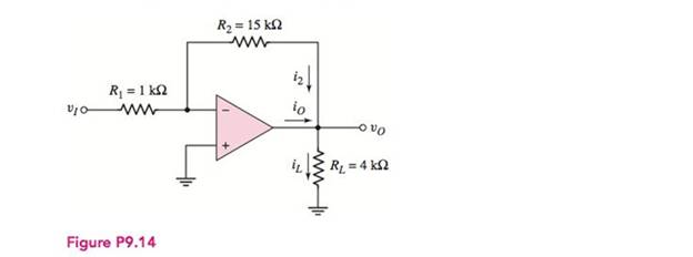
(a) The input to the circuit shown in Figure P9.14 is
(a)
The value of the output voltage
Answer to Problem 9.14P
The value of the voltage
Explanation of Solution
Calculation:
The given diagram is shown in Figure 1
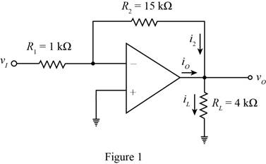
Apply KCL at the inverting terminal.
Substitute
The expression for the value of the current
Substitute
The expression for the value of the current
Substitute
The expression for the value of the current
Substitute
Conclusion:
Therefore, the value of the voltage
(b)
The value of the output voltage
Answer to Problem 9.14P
The value of the voltage
Explanation of Solution
Calculation:
The expression for the output voltage is given by,
Substitute
The expression for the value of the current
Substitute
The expression for the value of the current
Substitute
The conversion from
The conversion from
The conversion from
The expression for the value of the current
Substitute
Conclusion:
Therefore, the value of the voltage
(c)
The value of the output voltage
Answer to Problem 9.14P
The value of the voltage
Explanation of Solution
Calculation:
The conversion from
The conversion from
The expression for the output voltage is given by,
Substitute
The expression for the value of the current
Substitute
The expression for the value of the current
Substitute
The expression for the value of the current
Substitute
Conclusion:
Therefore, the value of the voltage
Want to see more full solutions like this?
Chapter 9 Solutions
Microelectronics: Circuit Analysis and Design


- What the effect of zeta on the damping?arrow_forwardA circuit is constructed with an AC generator, a resistor, capacitor and inductor as shown. The generator voltage varies in time as ε =Va - Vb = εmsinωt, where εm = 120 V and ω = 726 radians/second. The values for the remaining circuit components are: R = 62 Ω, L = 95.6 mH, and C = 13.8μF. 4) What is t1, the first time after t = 0 when the voltage across the inductor is zero? 6) What is VC = Vd - Va, the voltage across the capacitor, at time t = 0? Note that VC is a signed number.arrow_forwardAn exponential signal has initial value Vi=v(0)=-3[V], final value Vf=(∞)=6[V], and a time constant of 10s. Determine: a) the equation for v(t) b) Graph the function for 0≤t≤100 sec, together with a table of values at 10s (or less) time intervals.arrow_forward
- Consider the circuit diagram below. Compute the impedances for all circuit components, i.e. ??1, ??2, ??3, ??1, ??1, for (a) ? =60 Hz, (b) ?=100 Hz. For both (a) and (b), redraw the circuit diagram with the computed impedances indicated. Express your final answers as a phasors with rectangular coordinates. You must show your all your work for the complex matharrow_forwardA resistor, an inductor, and a capacitor are connected in parallel to an ac source with voltage amplitude V and angular frequency v. Let the source voltage be given by v = Vcosvt. (a) Show that each of the instantaneous voltages vR, vL, and vC at any instant is equal to v and that i = iR + iL + iC, where i is the current through the source and iR, iL, and iC are the currents through the resistor, inductor, and capacitor, respectively. (b) What are the phases of iR, iL, and iC with respect to v? Use current phasors to represent i, iR, iL, and iC. In a phasor diagram, show the phases of these four currents with respect to v. (c) Use the phasor diagram of part (b) to show that the current amplitude I for the current i through the source is I = √(I2R) + (IC - IL)2 . (d) Show that the result of part (c) can be written as I = V/Z, with 1/Z = √ (1/R2) + [ωC - (1/ωL)]2.arrow_forwardSwitch U1 is closed at t=0 Initial voltage C1=3V C2=0V 1. Derive governing equation for t>0 2. Characteristics equation t>0 3. Natural response t>0 4. Natural frequency and time constant 5.plot transient response 5 time constantsarrow_forward
- What are two real-world consequences of having to amplify the input to a system so that the output reaches a desired steady-state value? Related to Electroncis & Circuitsarrow_forwardBy Differential equations An electromotive force of 100 volts is applied to an RC series circuit, in which the resistance is 50 ohms and the capacitance is 0.002 farads. Determine the load q(t) of the capacitor, if q(0) = 5C. Find the current i(t). Pls dont skip any steps even on the integralsarrow_forwardFor the circuit in the figure, initially the switch S is closed in (b), until the capacitor is charged; then the switch goes to point (a) so that the battery is disconnected and the capacitor, resistor and inductor are connected in series. Once S is connected at point (a), find a) the angular frequency of oscillation for the series circuit b) write the equation for the charge on the capacitor as a function of time with the respective values of Qmax, angular frequency Wd and time T c) make the Q(t) graph showing explicitly the envelope of the exponential decay (Hint: use geogebra or an application of your choice to obtain a graph).arrow_forward
- Q5. For an exhibition project you are designing a circuit of signal processor which can be connected to 230V, 50 Hz supply have a 5.0 H inductor, 80 μ F capacitor and 40Ω resistor kept in series. How can you evaluate the rms current and average power delivered to the circuit? Based on your observation, evaluate the potential drop across capacitance and inductor. Comment about that r m s voltage found in this circuit is less than peak voltage? Justify it with your answer. If you remove the inductor and connect a bulb in series with a capacitor. What will happen to the brightness of bulb if it is connected to DC source and then to an AC source. Assess and find reason for your observations in each case.arrow_forwardWhen the average real power absorbed by an impedance is zero, then the impedance is: Select one: a. A parallel combination of resistors and capacitors b. An ideal resistor c. A pure inductor d. A resistor in parallel to an inductor e. A resistor in parallel to a capacitorarrow_forwardDescribe the steady-state similarities and differences of DC and AC circuits with purelyresistive elementsarrow_forward
 Introductory Circuit Analysis (13th Edition)Electrical EngineeringISBN:9780133923605Author:Robert L. BoylestadPublisher:PEARSON
 Delmar's Standard Textbook Of ElectricityElectrical EngineeringISBN:9781337900348Author:Stephen L. HermanPublisher:Cengage Learning
 Programmable Logic ControllersElectrical EngineeringISBN:9780073373843Author:Frank D. PetruzellaPublisher:McGraw-Hill Education
 Fundamentals of Electric CircuitsElectrical EngineeringISBN:9780078028229Author:Charles K Alexander, Matthew SadikuPublisher:McGraw-Hill Education
 Electric Circuits. (11th Edition)Electrical EngineeringISBN:9780134746968Author:James W. Nilsson, Susan RiedelPublisher:PEARSON
 Engineering ElectromagneticsElectrical EngineeringISBN:9780078028151Author:Hayt, William H. (william Hart), Jr, BUCK, John A.Publisher:Mcgraw-hill Education,