
Concept explainers
Videos
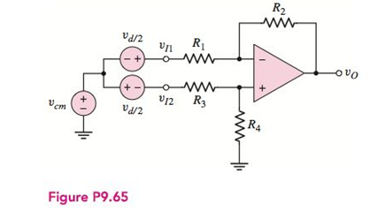
The circuit in Figure P9.65 is a representation of the common-mode and differential-input signals to a difference amplifier. The output voltage can bewritten as
(a) Setting
(b) Determine
(a)
To show: The expression for the common mode gain is
Explanation of Solution
Calculation:
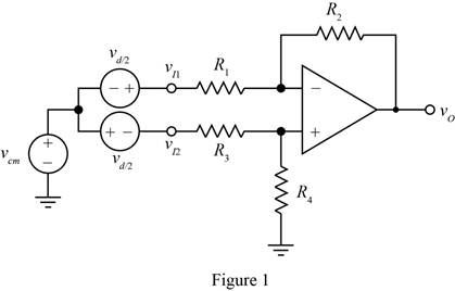
The given diagram is shown in Figure 1.
The expression for the voltage
The expression for the value of the voltage
The expression for the value of the voltage
The expression for the voltage
Apply KCL at the inverting terminal.
Substitute
Substitute
The expression for the output voltage is given by
Substitute
Substitute
Conclusion:
Therefore, theexpression for the common mode gain is
(b)
The value of common mode voltage gain.
Answer to Problem 9.65P
The value of the common mode voltage gain is
Explanation of Solution
Calculation:
The expression for the value of common voltage gain is given by
Substitute
Conclusion:
Therefore, the value of the common mode voltage gain is
(c)
The value of common mode voltage gain.
Answer to Problem 9.65P
The value of the common mode voltage gain is
Explanation of Solution
Calculation:
The expression for the value of common voltage gain is given by
For
Substitute
Conclusion:
Therefore, the value of the common mode voltage gain is
Want to see more full solutions like this?
Chapter 9 Solutions
Microelectronics: Circuit Analysis and Design


- Determine the closed-loop voltage gain of the circuit shown in the figure assumingan ideal op amparrow_forwardDraw the circuit diagram of the basic inverting amplifier configuration. Give an expression for the closed-loop voltage gain of the circuit in terms of the resistances, assuming an ideal op amp. Give expressions for the input impedance and output impedance of the circuit.arrow_forwardSuppose that we are designing an amplifier, using an op amp. What problems are associated with using very small feedback resistances? With very large feedback resistances?arrow_forward
- Draw and interpret the gain-frequency graph of the op-amp circuit given in the figure.arrow_forwardPlease answer this two part question A) It is known that when an Op-amp is operated using the negative feedbackconfiguration, the output impedance reduces. Derive an expression that proves this. B) It is known that when an Op-amp is operated using the positive feedbackconfiguration, the output impedance increase. Derive an expression that proves this.arrow_forwardWhich op-amp network is commonly used to reduce the effect of noise on comparator circuits (Schmitt trigger arrangement)?Using an output networkUsing a negative feedback networkUsing an input networkUsing a positive feedback networkarrow_forward
- The op amp in the circuit of Figure is ideal.a) What op amp circuit configuration is this?b) Find ?0 in terms of ??.c) Find the range of values for ?? such that ?0 does not saturate and the op ampremains in its linear region of operation.arrow_forward1. A non-inverting op-amp circuit has the open loop gain of 105 and the resistances R1 = 1k Ω and R2 = 39k Ω . Calculate (a) The actual value of voltage gain, (b) Considering the finite open loop gain, the ideal value of gain, and (c) The percentage error, when ideal voltage gain is compared with actual voltage gain.arrow_forwardThe upper critical frequency of an op-amp’s open-loop response is 200 Hz. If the midrange gain is 175,000, answer the following: What is the ideal gain at 200 Hz? What is the actual gain? What is the op-amp’s open-loop bandwidth?arrow_forward
- An inverting op – amplifier stage is designed with an input resistance of 5 KΩ and feedback resistance of 10 KΩ. The load resistance is 100 Ω with DC gain of 5x10^4 . The output internal resistance is 500 Ω while the input impedance is infinity, assuming an input voltage of 1.5 volts, calculate the following ?a) The AC gain ?b) The output voltage ?c) The looking back resistance ?arrow_forwardAn op-amp has the open-loop frequency responseshown in Figure 8.37 in the text. What is theapproximate bandwidth of a circuit that uses theop-amp with a closed-loop gain of 75? What is thebandwidth if the gain is 350?arrow_forwarda) Given a non inverting op – amp below, what should be the operating frequency to have a high frequency gain of 10 % lower that the mid band gain. Assume a DC gain of 40 dB & it will start to sag @ 20 KHz.? b) calculate the high frequency gain @ 25 KHz in dB with same given as in (a) ? c) calculate the normalize gain?arrow_forward
 Introductory Circuit Analysis (13th Edition)Electrical EngineeringISBN:9780133923605Author:Robert L. BoylestadPublisher:PEARSON
 Delmar's Standard Textbook Of ElectricityElectrical EngineeringISBN:9781337900348Author:Stephen L. HermanPublisher:Cengage Learning
 Programmable Logic ControllersElectrical EngineeringISBN:9780073373843Author:Frank D. PetruzellaPublisher:McGraw-Hill Education
 Fundamentals of Electric CircuitsElectrical EngineeringISBN:9780078028229Author:Charles K Alexander, Matthew SadikuPublisher:McGraw-Hill Education
 Electric Circuits. (11th Edition)Electrical EngineeringISBN:9780134746968Author:James W. Nilsson, Susan RiedelPublisher:PEARSON
 Engineering ElectromagneticsElectrical EngineeringISBN:9780078028151Author:Hayt, William H. (william Hart), Jr, BUCK, John A.Publisher:Mcgraw-hill Education,