
Introductory Circuit Analysis (13th Edition)
13th Edition
ISBN: 9780133923605
Author: Robert L. Boylestad
Publisher: PEARSON
expand_more
expand_more
format_list_bulleted
Videos
Textbook Question
Chapter 9, Problem 37P
a. For the network in Fig.9.149, determine the value of R2 for maximum power to R4.
b. Is there a general statement that can be made about situations such as those presented here and in Problem 36?
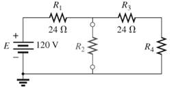
Fig.9.149
Expert Solution & Answer
Want to see the full answer?
Check out a sample textbook solution
Students have asked these similar questions
A certain practical current source provides 1.225 W to a 10 2 load. That same practical current source provides 0.644444444444444
W to an 580 S load. If the same practical current source had a resistance R, is connected to it, creating a voltage across R, of vL
and a current through RL of iL. Find the values of RL, VL, and i, if
(a) vL X iL is maximum
(b) vỊ, is a maximum
(c) iL is a maximum.
a)Write the relationship between V1 , R1 , Rc and Ic .b) Write the relationship between V2 , R2 , Rc and Ic .c) Write the relationship between V3 , R3 , Rc and Ic .d) Determine the values of Rc and Ic .e) Determine the value of R3 .
9:..
o Quiz-1 prac..
O/ For the circuit shown below, find the following:
1- Voltage drop across the resistance 122 by using
Kirchhoff's laws.
2- Power consumed in the resistance 32.
R3
120
R2
30
BAT1
18 V
BAT2
60
21 VT
R4
20
Chapter 9 Solutions
Introductory Circuit Analysis (13th Edition)
Ch. 9 - (a) Using the superposition theorem, determine the...Ch. 9 - a. Using the superposition theorem, determine the...Ch. 9 - Using the superposition theorem, determine the...Ch. 9 - Using superposition, find the current l through...Ch. 9 - Using superposition, find the voltage VR3 for the...Ch. 9 - Using superposition, find the voltage V2 for the...Ch. 9 - Using superposition, find the current through R1...Ch. 9 - Using superposition, find the voltage across the...Ch. 9 - a. Find the Thévenin equivalent circuit for the...Ch. 9 - a. Find the Thévenin equivalent circuit for the...
Ch. 9 - a. Find the Thévenin equivalent circuit for the...Ch. 9 - Find the Thévenin equivalent circuit for the...Ch. 9 - Find the Thévenin equivalent circuit for the...Ch. 9 - Find the Thévenin equivalent circuit for the...Ch. 9 - a. Find the Thévenin equivalent circuit for the...Ch. 9 - Determine the Thevénin equivalent circuit for the...Ch. 9 - a. Determine the Thévenin equivalent circuit for...Ch. 9 - For the network in Fig. 9.142, find the Thévenin...Ch. 9 - For the transistor network in Fig. 9.143. a. Find...Ch. 9 - For each vertical set of measurements appearing in...Ch. 9 - For the network of Fig.9.145, find the Thévenin...Ch. 9 - a. Find the Norton equivalent circuit for the...Ch. 9 - a. Find the Norton equivalent circuit for the...Ch. 9 - Find the Norton equivalent circuit for the network...Ch. 9 - Find the Norton equivalent circuit for the network...Ch. 9 - Find the Norton equivalent circuit for the network...Ch. 9 - Find the Norton equivalent circuit for the network...Ch. 9 - Find the Norton equivalent circuit for the network...Ch. 9 - Find the Norton equivalent circuit for the network...Ch. 9 - a. Find the Norton equivalent circuit external to...Ch. 9 - a. Find the value of R for maximum power transfer...Ch. 9 - a. Find the value of R for maximum power transfer...Ch. 9 - a. Find the value of R for maximum power transfer...Ch. 9 - a. Find the value of RL in Fig.9.142 for maximum...Ch. 9 - a. For the network of Fig. 9.147, determine the...Ch. 9 - Find the resistance R1 in Fig.9.148 such that the...Ch. 9 - a. For the network in Fig.9.149, determine the...Ch. 9 - For the network in Fig. 9.150, determine the level...Ch. 9 - Using Millmans theorem, find the current through...Ch. 9 - Repeat Problem 38 for the network in Fig.9.152....Ch. 9 - Using Millmans theorem, find the current through...Ch. 9 - Using the dual of Millmans theorem, find the...Ch. 9 - Using the dual of Millmans theorem, find the...Ch. 9 - Using the substitution theorem, draw three...Ch. 9 - Using the substituion theorem, draw three...Ch. 9 - Using the substitution theorem, draw three...Ch. 9 - a. For the network in Fig. 9.159(a), determine the...Ch. 9 - a. For the network of Fig.9.16(a), determine the...Ch. 9 - a. Determine the voltageV for the network in...Ch. 9 - Using PSpice or Multisim and the superposition...Ch. 9 - Using PSpice or Multisim, determine the Thévenin...Ch. 9 - a. Using PSpice, plot the power delivered to the...Ch. 9 - Change the 300 resistor in Fig. 9.145 to a...
Knowledge Booster


Learn more about
Need a deep-dive on the concept behind this application? Look no further. Learn more about this topic, electrical-engineering and related others by exploring similar questions and additional content below.Similar questions
- An independent voltage source is characterized by a terminal voltage which Select one: a. is completely independent of the current through it. on b. is completely independent of the power dissipated by it. c. is completely dependent on the current through it. d. None of the abovearrow_forwardWrite the KCL equations for the circuit shown Node b:Node c: Node g: Node f:arrow_forward16. Determine the Equivalent Resistance R, for the circuit below. 3502 1002 4002 2002 12V 5002 3002 2502 502 1502arrow_forward
- electrical engineering Find V1, V2, V3, and V4. choices a.) V1= 10 V, V2= 9.278 V, V3= 8.1 V; V4= 9.817 V b.) V1= 11.9 V, V2= 9.1 V, V3= 8.1 V; V4= 9.817 V c.) V1= 10 V, V2= 9.1 V, V3= 3.271 V; V4= 9.817 V d.) V1= 10 V, V2= 1.367 V, V3= 8.1 V; V4= 9.817 V e.) V1= 10 V, V2= 9.1 V, V3= 3.41 V; V4= 9.817 V f.) V1= 10 V, V2= 5.1 V, V3= 1.1 V; V4= 3.817 V g.) V1= 10 V, V2= 6.28 V, V3= 4.884 V; V4= 5.001 Varrow_forwardQ3) For the network shown in the figure below, determine the following: a) fe b) Zinl and Zin2 c) Zo1 and Zo2 d) Avı, Av2, and AVT +20 V 6.8 kQ 30 ka 6.8 ka 30 ka 0.5 F 0.5 uF P-150 B- 150 1.5 ka 50 uF 1.5 ka 50 uFarrow_forwardRefer to the following circuit diagram. Find the current Is1 supplied by source E₁. and current Is2 supplied by E2. E₁ 130V Ist A Z₁ 3352 N Z₂ 1052 B D Z₁ 2402 Z 502 C Isz E₂ 110Varrow_forward
- Find node voltages if (1) v2 reference (2) v4 reference (3) v5 reference Answer all subparts..arrow_forwardNormally, you would construct the KCL equations for each nonreference essential node using the same equation format. For the final KCL equation at the node labeled vg, assume that the current through the 120 V source is entering the node and that the currents through the 8 kN and 5 k2 resistors leave the node. Construct the KCL equation by setting the sum of the currents entering equal to the sum of the currents leaving. Then move all of the terms to one side of the equation, so that the other side contains "= 0." Recall that, in this circuit, = 10 mA and v = 120 V. 5 kN + V. 1 kQ 8 kQ V2 V3 3 k2 v. 2 kΩ Express your answer in terms of v1, v2, and vg . Make sure each term is expressed in amperes.arrow_forwardFind 8 ohm resistance current with Thevenin’s equivaleny circuit. please do. then explain to me thanksarrow_forward
- Plz do your own solution don't copy from others . show the solution with details plz.arrow_forwardIn the given circuit, find the value of unknown resistor R8, using any principle of DC circuit. Given: R3=2 ohm, R4= 2 ohm, R5= 2 ohm, R6= 5 ohm, R7=1 ohm, R9= 2 ohm, current in R5= 3A and current in R9= 6A RI 5, R2 Select one: a. None of these b. 2 ohm c. 1 ohm d. 6 ohmarrow_forwardConsider the circuit shown in below Figure, Find values of the resistances R1 and R2 that cause the voltages v1 and v2 to be v1 = 1 V and v2 = 2 V. 500 2 + + R1 R2 () 5 mA 3 mA V1 V2 6:03 PM 50°F Clear 2/18/2022 P Type here to search Del End F10 PgUp. F11 PgDn F12 PrtScn Home F7 F2 F3 F1 & ) Backspace %23 %24 % 4. 5 7 8. 9. 2 3 W.arrow_forward
arrow_back_ios
SEE MORE QUESTIONS
arrow_forward_ios
Recommended textbooks for you
 Introductory Circuit Analysis (13th Edition)Electrical EngineeringISBN:9780133923605Author:Robert L. BoylestadPublisher:PEARSON
 Delmar's Standard Textbook Of ElectricityElectrical EngineeringISBN:9781337900348Author:Stephen L. HermanPublisher:Cengage Learning
 Programmable Logic ControllersElectrical EngineeringISBN:9780073373843Author:Frank D. PetruzellaPublisher:McGraw-Hill Education
 Fundamentals of Electric CircuitsElectrical EngineeringISBN:9780078028229Author:Charles K Alexander, Matthew SadikuPublisher:McGraw-Hill Education
 Electric Circuits. (11th Edition)Electrical EngineeringISBN:9780134746968Author:James W. Nilsson, Susan RiedelPublisher:PEARSON
 Engineering ElectromagneticsElectrical EngineeringISBN:9780078028151Author:Hayt, William H. (william Hart), Jr, BUCK, John A.Publisher:Mcgraw-hill Education,
Introductory Circuit Analysis (13th Edition)
Electrical Engineering
ISBN:9780133923605
Author:Robert L. Boylestad
Publisher:PEARSON
Delmar's Standard Textbook Of Electricity
Electrical Engineering
ISBN:9781337900348
Author:Stephen L. Herman
Publisher:Cengage Learning
Programmable Logic Controllers
Electrical Engineering
ISBN:9780073373843
Author:Frank D. Petruzella
Publisher:McGraw-Hill Education
Fundamentals of Electric Circuits
Electrical Engineering
ISBN:9780078028229
Author:Charles K Alexander, Matthew Sadiku
Publisher:McGraw-Hill Education
Electric Circuits. (11th Edition)
Electrical Engineering
ISBN:9780134746968
Author:James W. Nilsson, Susan Riedel
Publisher:PEARSON
Engineering Electromagnetics
Electrical Engineering
ISBN:9780078028151
Author:Hayt, William H. (william Hart), Jr, BUCK, John A.
Publisher:Mcgraw-hill Education,
Millman's Theorem Derivation; Author: ElectronX Lab;https://www.youtube.com/watch?v=heH-s04M0jo;License: Standard Youtube License