
Introductory Circuit Analysis (13th Edition)
13th Edition
ISBN: 9780133923605
Author: Robert L. Boylestad
Publisher: PEARSON
expand_more
expand_more
format_list_bulleted
Concept explainers
Videos
Textbook Question
Chapter 9, Problem 7P
Using superposition, find the current through
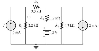
Fig.9.131
Expert Solution & Answer

Trending nowThis is a popular solution!

Students have asked these similar questions
3. Using superposition, find the current through R for
cach network of Fig. 9.125.
R2
3.3 kN
Ig
D RE2.2 kN
4.7 k2
8 V
5 mA
(a)
9.35 For the following network determine:
a) The value or R that will draw maximum power from the source.
b) Determine the value of the maximum power drawn by R.
R 2.4 N
5A R{ 24 N R
20 V
31. a. Find the value of R for maximum power transfer to R forthe network of Fig. 9.133.b. Determine the maximum power of R
Chapter 9 Solutions
Introductory Circuit Analysis (13th Edition)
Ch. 9 - (a) Using the superposition theorem, determine the...Ch. 9 - a. Using the superposition theorem, determine the...Ch. 9 - Using the superposition theorem, determine the...Ch. 9 - Using superposition, find the current l through...Ch. 9 - Using superposition, find the voltage VR3 for the...Ch. 9 - Using superposition, find the voltage V2 for the...Ch. 9 - Using superposition, find the current through R1...Ch. 9 - Using superposition, find the voltage across the...Ch. 9 - a. Find the Thévenin equivalent circuit for the...Ch. 9 - a. Find the Thévenin equivalent circuit for the...
Ch. 9 - a. Find the Thévenin equivalent circuit for the...Ch. 9 - Find the Thévenin equivalent circuit for the...Ch. 9 - Find the Thévenin equivalent circuit for the...Ch. 9 - Find the Thévenin equivalent circuit for the...Ch. 9 - a. Find the Thévenin equivalent circuit for the...Ch. 9 - Determine the Thevénin equivalent circuit for the...Ch. 9 - a. Determine the Thévenin equivalent circuit for...Ch. 9 - For the network in Fig. 9.142, find the Thévenin...Ch. 9 - For the transistor network in Fig. 9.143. a. Find...Ch. 9 - For each vertical set of measurements appearing in...Ch. 9 - For the network of Fig.9.145, find the Thévenin...Ch. 9 - a. Find the Norton equivalent circuit for the...Ch. 9 - a. Find the Norton equivalent circuit for the...Ch. 9 - Find the Norton equivalent circuit for the network...Ch. 9 - Find the Norton equivalent circuit for the network...Ch. 9 - Find the Norton equivalent circuit for the network...Ch. 9 - Find the Norton equivalent circuit for the network...Ch. 9 - Find the Norton equivalent circuit for the network...Ch. 9 - Find the Norton equivalent circuit for the network...Ch. 9 - a. Find the Norton equivalent circuit external to...Ch. 9 - a. Find the value of R for maximum power transfer...Ch. 9 - a. Find the value of R for maximum power transfer...Ch. 9 - a. Find the value of R for maximum power transfer...Ch. 9 - a. Find the value of RL in Fig.9.142 for maximum...Ch. 9 - a. For the network of Fig. 9.147, determine the...Ch. 9 - Find the resistance R1 in Fig.9.148 such that the...Ch. 9 - a. For the network in Fig.9.149, determine the...Ch. 9 - For the network in Fig. 9.150, determine the level...Ch. 9 - Using Millmans theorem, find the current through...Ch. 9 - Repeat Problem 38 for the network in Fig.9.152....Ch. 9 - Using Millmans theorem, find the current through...Ch. 9 - Using the dual of Millmans theorem, find the...Ch. 9 - Using the dual of Millmans theorem, find the...Ch. 9 - Using the substitution theorem, draw three...Ch. 9 - Using the substituion theorem, draw three...Ch. 9 - Using the substitution theorem, draw three...Ch. 9 - a. For the network in Fig. 9.159(a), determine the...Ch. 9 - a. For the network of Fig.9.16(a), determine the...Ch. 9 - a. Determine the voltageV for the network in...Ch. 9 - Using PSpice or Multisim and the superposition...Ch. 9 - Using PSpice or Multisim, determine the Thévenin...Ch. 9 - a. Using PSpice, plot the power delivered to the...Ch. 9 - Change the 300 resistor in Fig. 9.145 to a...
Additional Engineering Textbook Solutions
Find more solutions based on key concepts
Assume a telephone signal travels through a cable at two-thirds the speed of light. How long does it take the s...
Electric Circuits (10th Edition)
What is the color code for a 365- five-band precision resistor with a tolerance of 5 percent?
ELECTRICITY FOR TRADES (LOOSELEAF)
Design an ideal inverting op-amp circuit such that the voltage gain is Av=25 . The maximum current in any resis...
Microelectronics: Circuit Analysis and Design
Does the severity of an electric shock increase ordecrease with eh of the following changes? a. A decrease in t...
Electric Motors and Control Systems
The current source in the circuit shown generates the current pulse
Find (a) v (0); (b) the instant of time gr...
Electric Circuits. (11th Edition)
Identify the type of input and output configuration for each diff-amp in Figure 18-35.
Electronics Fundamentals: Circuits, Devices & Applications
Knowledge Booster


Learn more about
Need a deep-dive on the concept behind this application? Look no further. Learn more about this topic, electrical-engineering and related others by exploring similar questions and additional content below.Similar questions
- 33. a. Find the value of R for maximum power transfer to R for the network of Fig. 9.138 O. b. Determine the maximum power to R. 6Ω R 2Ω 2 A 3Ω Fig. 9.138arrow_forward• 1- a. For the network of Fig. 9.136, determine the value of R for maximum power to R. b. Determine the maximum power to R. c. Plot a curve of power to R versus R for R equal to . 1, 14. 14, 14, and 2 times the value obtained in 1(SA R4n E 24 V part (a). FIG. 9.136arrow_forward22. a. Find the Norton equivalent circuit for the network externalto the resistor R in Fig. 9.133.b. Convert the Norton equivalent circuit to the Thévenin form.c. Find the Thévenin equivalent circuit using the Théveninapproach and compare results with part (b)arrow_forward
- a. For the network of Fig. 9.136, determine the value of R for maximum power to R. b. Determine the maximum power to R. c. Plot a curve of power to R versus R for R equal to . 1, 14. 14. 14, and 2 times the value obtained in part (a). SA R40 E 24 V FIG. 9.136arrow_forwardHW • 1- a. For the network of Fig. 9.136, determine the value of R for maximum power to R b. Determine the maximum power to R. c. Plot a curve of power to R versus R for R equal to . R40 SA R4 24 V 1. 1 1 1 and 2 times the value obtained in part (a). FIG. 9.136arrow_forwardHW • 1- a. For the network of Fig. 9.136, determine the value of R for maximum power to R b. Determine the maximum power to R. c. Plot a curve of power to R versus R for R equal to . 1,14 14, 14, and 2 times the value obtained in part (a). SA Rn 24 V FIG. 9,136arrow_forward
- 15. a. Find the Thévenin equivalent circuit for the portions of the network of Fig. 9.139 external to points a and b. b. Redraw the network with the Thévenin circuit in place and find the current through the 10 kN resistor. 4 kN 4 kΩ 20 V 4 kΩ 10 kN 8 mA 4 kΩ FIG. 9.139arrow_forward6. Using superposition, find the voltage V2 for the network in Fig. 9.130 O. EO 36 V R1 12 kΩ 6.8 kN V2 R2 9 mA Fig. 9.130 Problem 6.arrow_forwarda. For the network of Fig. 9.136, determine the value of R for maximum power to R. b. Determine the maximum power to R. c. Plot a curve of power to R versus R for R equal to . 1 1, 14, 14, 14, and 2 times the value obtained in part (a). R1 4Ω SA R40 R E 24 V FIG. 9.136arrow_forward
- d) Terminal A is negative with respect to ter- minals C and D. TEST YOUR KNOWLEDGE Refer to the voltage divider circuit shown in Fig. 9-3. The source voltage is 100Vde and the ammeter indicates a current of .02Ade. Resistor R, is 3000 ohms and the voltage Ec.p between 1. terminals C and D is (30Vdc. Calculate the following: 3. Refer to Fig. 9-1. If the value of resistor Rs was changed to 6.5 kilohms, calculate the following: a) R, = b) E4-5 " Vdc circuit current I c) Eg.c =. Vde d) R; = mAde I=.02 A Vdc 30y de Oc 100vde Vdc Vdc Fig. 9-3 4. The sum of the voltage drops in a series circuit is equal to 2. State whether the following statements regarding Fig. 9-3 are true or false. a) Terminal B is negative with respect to ter- 5. State the algebraic form of Kirchhoff's Law minal A. b) Terminal C is positive with respect to ter- minal B. c) A voltmeter connected between terminals A and C would measure 40Vde,arrow_forwardHW • 1- a. For the network of Fig. 9.136, determine the value of R for maximum power to R. b. Determine the maximum power to R. c. Plot a curve of power to R versus R for R equal to . 1. 14, 14. 14, and 2 times the value obtained in part (a). SA R40 R 24 V FIG. 9.136 *4.75 For the circuit in Fig. 4.141, determine the value of R such that the maximum power delivered to the load is 3 mw. R R ww- R ww IV II wwarrow_forward• 1- a. For the network of Fig. 9.136, determine the value of R for maximum power to R. b. Determine the maximum power to R. c. Plot a curve of power to R versus R for R equal to . 1, 14. 14, 14, and 2 times the value obtained in part (a). RE 40 SA R 4 E 24 V FIG. 9.136arrow_forward
arrow_back_ios
SEE MORE QUESTIONS
arrow_forward_ios
Recommended textbooks for you
 Introductory Circuit Analysis (13th Edition)Electrical EngineeringISBN:9780133923605Author:Robert L. BoylestadPublisher:PEARSON
 Delmar's Standard Textbook Of ElectricityElectrical EngineeringISBN:9781337900348Author:Stephen L. HermanPublisher:Cengage Learning
 Programmable Logic ControllersElectrical EngineeringISBN:9780073373843Author:Frank D. PetruzellaPublisher:McGraw-Hill Education
 Fundamentals of Electric CircuitsElectrical EngineeringISBN:9780078028229Author:Charles K Alexander, Matthew SadikuPublisher:McGraw-Hill Education
 Electric Circuits. (11th Edition)Electrical EngineeringISBN:9780134746968Author:James W. Nilsson, Susan RiedelPublisher:PEARSON
 Engineering ElectromagneticsElectrical EngineeringISBN:9780078028151Author:Hayt, William H. (william Hart), Jr, BUCK, John A.Publisher:Mcgraw-hill Education,
Introductory Circuit Analysis (13th Edition)
Electrical Engineering
ISBN:9780133923605
Author:Robert L. Boylestad
Publisher:PEARSON
Delmar's Standard Textbook Of Electricity
Electrical Engineering
ISBN:9781337900348
Author:Stephen L. Herman
Publisher:Cengage Learning
Programmable Logic Controllers
Electrical Engineering
ISBN:9780073373843
Author:Frank D. Petruzella
Publisher:McGraw-Hill Education
Fundamentals of Electric Circuits
Electrical Engineering
ISBN:9780078028229
Author:Charles K Alexander, Matthew Sadiku
Publisher:McGraw-Hill Education
Electric Circuits. (11th Edition)
Electrical Engineering
ISBN:9780134746968
Author:James W. Nilsson, Susan Riedel
Publisher:PEARSON
Engineering Electromagnetics
Electrical Engineering
ISBN:9780078028151
Author:Hayt, William H. (william Hart), Jr, BUCK, John A.
Publisher:Mcgraw-hill Education,
Kirchhoff's Rules of Electrical Circuits; Author: Flipping Physics;https://www.youtube.com/watch?v=d0O-KUKP4nM;License: Standard YouTube License, CC-BY