
Introductory Circuit Analysis (13th Edition)
13th Edition
ISBN: 9780133923605
Author: Robert L. Boylestad
Publisher: PEARSON
expand_more
expand_more
format_list_bulleted
Videos
Textbook Question
Chapter 9, Problem 15P
a. Find the Thévenin equivalent circuit for the portions of the network of Fig.9.139 external to points a and b.
b. Redraw the network with the Thevenin circuit in place and find the current through the 10k
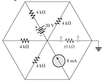
Figure.9.139
Expert Solution & Answer
Want to see the full answer?
Check out a sample textbook solution
Students have asked these similar questions
Determine the equivalent resistance between terminals a and b.
9.6540 Q
8.2756Q
9.2715Q
O 8.3025 Q
R5
5 Ohms
.R1
www
1 Ohm
R2
2 Ohms
R6
6 Ohms
R3
3 Ohms
www
R4
4 Ohms
*16. a. Determine the Thevénin equivalent circuit for the net-
work external to the resistor R in Fig. 9.140.
b. Find the current through the resistor R if its value is
20 Ω, 50 Ω, and 100 Ω
c. Without having the Thévenin equivalent circuit, what
would you have to do to find the current through the
resistor R for all the values of part (b)?
R1
R3
R5
20 Ω
12 N
20
E
20 V R2
R4
16 N
R
FIG. 9.140
2s.
IX. Refer to Figure 9. Switch Si in the circuit below is closed at t=0, and switch S2 is closed at t =
1. Find i(t) for all t.
2. Find i(1) and i(5).
Chapter 9 Solutions
Introductory Circuit Analysis (13th Edition)
Ch. 9 - (a) Using the superposition theorem, determine the...Ch. 9 - a. Using the superposition theorem, determine the...Ch. 9 - Using the superposition theorem, determine the...Ch. 9 - Using superposition, find the current l through...Ch. 9 - Using superposition, find the voltage VR3 for the...Ch. 9 - Using superposition, find the voltage V2 for the...Ch. 9 - Using superposition, find the current through R1...Ch. 9 - Using superposition, find the voltage across the...Ch. 9 - a. Find the Thévenin equivalent circuit for the...Ch. 9 - a. Find the Thévenin equivalent circuit for the...
Ch. 9 - a. Find the Thévenin equivalent circuit for the...Ch. 9 - Find the Thévenin equivalent circuit for the...Ch. 9 - Find the Thévenin equivalent circuit for the...Ch. 9 - Find the Thévenin equivalent circuit for the...Ch. 9 - a. Find the Thévenin equivalent circuit for the...Ch. 9 - Determine the Thevénin equivalent circuit for the...Ch. 9 - a. Determine the Thévenin equivalent circuit for...Ch. 9 - For the network in Fig. 9.142, find the Thévenin...Ch. 9 - For the transistor network in Fig. 9.143. a. Find...Ch. 9 - For each vertical set of measurements appearing in...Ch. 9 - For the network of Fig.9.145, find the Thévenin...Ch. 9 - a. Find the Norton equivalent circuit for the...Ch. 9 - a. Find the Norton equivalent circuit for the...Ch. 9 - Find the Norton equivalent circuit for the network...Ch. 9 - Find the Norton equivalent circuit for the network...Ch. 9 - Find the Norton equivalent circuit for the network...Ch. 9 - Find the Norton equivalent circuit for the network...Ch. 9 - Find the Norton equivalent circuit for the network...Ch. 9 - Find the Norton equivalent circuit for the network...Ch. 9 - a. Find the Norton equivalent circuit external to...Ch. 9 - a. Find the value of R for maximum power transfer...Ch. 9 - a. Find the value of R for maximum power transfer...Ch. 9 - a. Find the value of R for maximum power transfer...Ch. 9 - a. Find the value of RL in Fig.9.142 for maximum...Ch. 9 - a. For the network of Fig. 9.147, determine the...Ch. 9 - Find the resistance R1 in Fig.9.148 such that the...Ch. 9 - a. For the network in Fig.9.149, determine the...Ch. 9 - For the network in Fig. 9.150, determine the level...Ch. 9 - Using Millmans theorem, find the current through...Ch. 9 - Repeat Problem 38 for the network in Fig.9.152....Ch. 9 - Using Millmans theorem, find the current through...Ch. 9 - Using the dual of Millmans theorem, find the...Ch. 9 - Using the dual of Millmans theorem, find the...Ch. 9 - Using the substitution theorem, draw three...Ch. 9 - Using the substituion theorem, draw three...Ch. 9 - Using the substitution theorem, draw three...Ch. 9 - a. For the network in Fig. 9.159(a), determine the...Ch. 9 - a. For the network of Fig.9.16(a), determine the...Ch. 9 - a. Determine the voltageV for the network in...Ch. 9 - Using PSpice or Multisim and the superposition...Ch. 9 - Using PSpice or Multisim, determine the Thévenin...Ch. 9 - a. Using PSpice, plot the power delivered to the...Ch. 9 - Change the 300 resistor in Fig. 9.145 to a...
Additional Engineering Textbook Solutions
Find more solutions based on key concepts
Analog Voltmeter Design Figure P2-98(a) shows a voltmeter circuit consisting of a D'Arsonval meter, two series ...
ANALYSIS+DESIGN OF LINEAR CIRCUITS(LL)
The voltage source of the circuit shown in Fig. P1.29 is given by s(t)=25cos(4104t45)(V). Obtain an expression ...
Fundamentals of Applied Electromagnetics (7th Edition)
A constant voltage of 10V is applied to a 50H inductance, as shown in Figure P3.51 Figure P3 51 The current in ...
Electrical Engineering: Principles & Applications (7th Edition)
Identify the type of input and output configuration for each diff-amp in Figure 18-35.
Electronics Fundamentals: Circuits, Devices & Applications
When travelers from the USA and Canada visit Europe, they encounter a different power distribution system. Wall...
Electric machinery fundamentals
Assume a telephone signal travels through a cable at two-thirds the speed of light. How long does it take the s...
Electric Circuits (10th Edition)
Knowledge Booster


Learn more about
Need a deep-dive on the concept behind this application? Look no further. Learn more about this topic, electrical-engineering and related others by exploring similar questions and additional content below.Similar questions
- An independent voltage source is characterized by a terminal voltage which Select one: a. is completely independent of the current through it. on b. is completely independent of the power dissipated by it. c. is completely dependent on the current through it. d. None of the abovearrow_forward1.2Solve the total resistance, total current, individual currents, and individual voltages of the following dc circuits. EngineeringElectrical EngineeringCircuit Theoryarrow_forward1. A pn junction has No = 1018 cm3 and NA = 3x101 cm3. a. Calculate Vbi at T= 300 °K b. Calculate Vbi at T= 450 °Karrow_forward
- + E≡ R₁ W 122 36 V R2 Fon 9A The current 12 due to 9A is .............Aarrow_forwardA:.0 docs.google.com If a circuit has two equal parallel resistances connecred to a 150V DC power source, then the P.D. exist between the mid-point of one resistance and a point that is one-third from the other resistance equal to --- 24 V O 30 V 28 V 25 V Oarrow_forward1. Given the DC Series Circuit below: R₁ = 30 kr m E=IVE M R₂ = 15k^ Mu R₂ = 60kλ a) Draw the DC Series Equivalent Circuit and use it to find the total current, IT. b) What are the currents, I1, I2 and 13? c) Find the voltages V1, V2 and V3 by using Ohm's Law. d) Find the voltages V1, V2 and V3 by using Voltage Divider Rule. e) Calculate the Total Power, PT dissipated in this circuit. f) Compute the power dissipated by each resistor, P1, P2 and P3.arrow_forward
- Preview File Edit View Go Tools Window Help 88% D Wed 9:06 PM A Laboratory 7 - Series-Parallel DC Circuits.pdf (page 6 of 7) – Edited Q Search ABP Aal D 2/ O T v Av b Other Bookmarks v Laboratory 7 - Series-Parallel... Assuming a 16 V dc supply is connected to the circuit as shown, calculate: I, l1, 12, V1, V2, V3, Va, and Vab- 4 Record the values in the table. Be sure to indicate the correct unit for each quantity. R1 R2 3.3kQ 2.2ka - + EE16V a + Vat + V. R3 4.7kO R4 V4 1kO Parameter Calculated Measured RT --- A 12 V1 V2 V3 V4 Vab 6 + R = 0.332 Privacy - Terms Teleranao 100 NOV ..arrow_forwardThe following are the readings taken while conducting an experiment on a wind turbine. what will be the value of open circuit voltage, if the short circuit current is 0.472 A, Maximum power point voltage is 5.32 V, Maximum power point current is 0.111 A and the fill factor is 0.599? Select one: a. 2080 mV b. 2.08 mV c. 8020 V d. 80.2 Varrow_forwardA series circuit of two pure elements has an applied voltage of 200sin(100t+30)V. Determine the resulting steady-state current of the two elements are:a) R = 300 L =2.5 Hb) R = 400, Xc= 150 c) R = 250, C = 100u d) R = 120, Xl=300arrow_forward
- An independent voltage source is characterized by a terminal voltage which Select one: a. None of the above b. is completely independent of the power dissipated by it. c. is completely independent of the current through it. d. is completely dependent on the current through it.arrow_forwardA dc power supply has a no-load voltage of 30 V, and a full-load voltage of 25 V at a full-load current of 1 A. Its output resistance and load regulation, respectively, are (A) 52 and 20% (C) 52 and 16.7% (B) 252 and 20% (D) 252 and 16.7%arrow_forwardConsider the circuit shown in the figure below, where R9.00 0, R, -8.000, and = 11.0 V 10.00 ww 2.00 12 www 5.000 www R₂ www (a) Find the voltage (in V) across R₁. Find the equivalent resistance in the circuit by applying the equations for resistances in series and parallel, and use your result and Ohm's law to determine the total current in the circuit. You can use this value to calculate the potential drop across the 2.00-0 resistor, and from this, find the voltage across R₁ V (b) Find the current (in A) in R x Use Ohm's law and your result from part (a) to determine the current through R.. A BOarrow_forward
arrow_back_ios
SEE MORE QUESTIONS
arrow_forward_ios
Recommended textbooks for you
 Introductory Circuit Analysis (13th Edition)Electrical EngineeringISBN:9780133923605Author:Robert L. BoylestadPublisher:PEARSON
 Delmar's Standard Textbook Of ElectricityElectrical EngineeringISBN:9781337900348Author:Stephen L. HermanPublisher:Cengage Learning
 Programmable Logic ControllersElectrical EngineeringISBN:9780073373843Author:Frank D. PetruzellaPublisher:McGraw-Hill Education
 Fundamentals of Electric CircuitsElectrical EngineeringISBN:9780078028229Author:Charles K Alexander, Matthew SadikuPublisher:McGraw-Hill Education
 Electric Circuits. (11th Edition)Electrical EngineeringISBN:9780134746968Author:James W. Nilsson, Susan RiedelPublisher:PEARSON
 Engineering ElectromagneticsElectrical EngineeringISBN:9780078028151Author:Hayt, William H. (william Hart), Jr, BUCK, John A.Publisher:Mcgraw-hill Education,
Introductory Circuit Analysis (13th Edition)
Electrical Engineering
ISBN:9780133923605
Author:Robert L. Boylestad
Publisher:PEARSON
Delmar's Standard Textbook Of Electricity
Electrical Engineering
ISBN:9781337900348
Author:Stephen L. Herman
Publisher:Cengage Learning
Programmable Logic Controllers
Electrical Engineering
ISBN:9780073373843
Author:Frank D. Petruzella
Publisher:McGraw-Hill Education
Fundamentals of Electric Circuits
Electrical Engineering
ISBN:9780078028229
Author:Charles K Alexander, Matthew Sadiku
Publisher:McGraw-Hill Education
Electric Circuits. (11th Edition)
Electrical Engineering
ISBN:9780134746968
Author:James W. Nilsson, Susan Riedel
Publisher:PEARSON
Engineering Electromagnetics
Electrical Engineering
ISBN:9780078028151
Author:Hayt, William H. (william Hart), Jr, BUCK, John A.
Publisher:Mcgraw-hill Education,
Lesson 2 - Source Transformations, Part 2 (Engineering Circuits); Author: Math and Science;https://www.youtube.com/watch?v=7gno74RhVGQ;License: Standard Youtube License