
Introductory Circuit Analysis (13th Edition)
13th Edition
ISBN: 9780133923605
Author: Robert L. Boylestad
Publisher: PEARSON
expand_more
expand_more
format_list_bulleted
Concept explainers
Videos
Textbook Question
Chapter 9, Problem 35P
a. For the network of Fig. 9.147, determine the value of R for maximum power to R.
b. Determine the maximum power to R.
c. Plot a curve of power to R versus R for R ranging from 1/4 to 2 times the value determined in part (a) using an increment of 1/4 the value of R. Does the curve verify the fact that the chosen value of R in part (a) will ensure maximum power transfer?
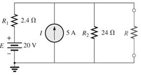
Fig. 9.147
Expert Solution & Answer
Want to see the full answer?
Check out a sample textbook solution
Students have asked these similar questions
Find equivalent resistance between A& Bin
the following circuits
(a)
A
www
22
B.
www
ww
22
The primary voltage (v1) necessary to supply a
240V load (v2) is
1:15
V1
V2
RL
Ideal
Select one:
a. 3600 V
b. -16 V
c. 16 V
d. -3600 V
Determine: Van, Vbn, Vcn, la, Ib, Ic and In. If the
source is worth 220v, its resistors are worth
16.13 ohms and its capacitors are 10 microF
B.
V
A
Zon
b
Zan
WHH
n
tv www
tw
A
Lo
DEB
Chapter 9 Solutions
Introductory Circuit Analysis (13th Edition)
Ch. 9 - (a) Using the superposition theorem, determine the...Ch. 9 - a. Using the superposition theorem, determine the...Ch. 9 - Using the superposition theorem, determine the...Ch. 9 - Using superposition, find the current l through...Ch. 9 - Using superposition, find the voltage VR3 for the...Ch. 9 - Using superposition, find the voltage V2 for the...Ch. 9 - Using superposition, find the current through R1...Ch. 9 - Using superposition, find the voltage across the...Ch. 9 - a. Find the Thévenin equivalent circuit for the...Ch. 9 - a. Find the Thévenin equivalent circuit for the...
Ch. 9 - a. Find the Thévenin equivalent circuit for the...Ch. 9 - Find the Thévenin equivalent circuit for the...Ch. 9 - Find the Thévenin equivalent circuit for the...Ch. 9 - Find the Thévenin equivalent circuit for the...Ch. 9 - a. Find the Thévenin equivalent circuit for the...Ch. 9 - Determine the Thevénin equivalent circuit for the...Ch. 9 - a. Determine the Thévenin equivalent circuit for...Ch. 9 - For the network in Fig. 9.142, find the Thévenin...Ch. 9 - For the transistor network in Fig. 9.143. a. Find...Ch. 9 - For each vertical set of measurements appearing in...Ch. 9 - For the network of Fig.9.145, find the Thévenin...Ch. 9 - a. Find the Norton equivalent circuit for the...Ch. 9 - a. Find the Norton equivalent circuit for the...Ch. 9 - Find the Norton equivalent circuit for the network...Ch. 9 - Find the Norton equivalent circuit for the network...Ch. 9 - Find the Norton equivalent circuit for the network...Ch. 9 - Find the Norton equivalent circuit for the network...Ch. 9 - Find the Norton equivalent circuit for the network...Ch. 9 - Find the Norton equivalent circuit for the network...Ch. 9 - a. Find the Norton equivalent circuit external to...Ch. 9 - a. Find the value of R for maximum power transfer...Ch. 9 - a. Find the value of R for maximum power transfer...Ch. 9 - a. Find the value of R for maximum power transfer...Ch. 9 - a. Find the value of RL in Fig.9.142 for maximum...Ch. 9 - a. For the network of Fig. 9.147, determine the...Ch. 9 - Find the resistance R1 in Fig.9.148 such that the...Ch. 9 - a. For the network in Fig.9.149, determine the...Ch. 9 - For the network in Fig. 9.150, determine the level...Ch. 9 - Using Millmans theorem, find the current through...Ch. 9 - Repeat Problem 38 for the network in Fig.9.152....Ch. 9 - Using Millmans theorem, find the current through...Ch. 9 - Using the dual of Millmans theorem, find the...Ch. 9 - Using the dual of Millmans theorem, find the...Ch. 9 - Using the substitution theorem, draw three...Ch. 9 - Using the substituion theorem, draw three...Ch. 9 - Using the substitution theorem, draw three...Ch. 9 - a. For the network in Fig. 9.159(a), determine the...Ch. 9 - a. For the network of Fig.9.16(a), determine the...Ch. 9 - a. Determine the voltageV for the network in...Ch. 9 - Using PSpice or Multisim and the superposition...Ch. 9 - Using PSpice or Multisim, determine the Thévenin...Ch. 9 - a. Using PSpice, plot the power delivered to the...Ch. 9 - Change the 300 resistor in Fig. 9.145 to a...
Additional Engineering Textbook Solutions
Find more solutions based on key concepts
With respect to the circuit in Fig. 5.90, (a) employ Thévenin’s theorem to determine the equivalent network see...
Loose Leaf for Engineering Circuit Analysis Format: Loose-leaf
A constant voltage of 10V is applied to a 50H inductance, as shown in Figure P3.51 Figure P3 51 The current in ...
Electrical Engineering: Principles & Applications (7th Edition)
The voltage source of the circuit shown in Fig. P1.29 is given by s(t)=25cos(4104t45)(V). Obtain an expression ...
Fundamentals of Applied Electromagnetics (7th Edition)
When travelers from the USA and Canada visit Europe, they encounter a different power distribution system. Wall...
Electric machinery fundamentals
Assume a telephone signal travels through a cable at two-thirds the speed of light. How long does it take the s...
Electric Circuits (10th Edition)
For the “tank” circuit in Fig. 14.79, find the resonant frequency.
Figure 14.79
For Probs. 14.39, 14.71, and 1...
Fundamentals of Electric Circuits
Knowledge Booster


Learn more about
Need a deep-dive on the concept behind this application? Look no further. Learn more about this topic, electrical-engineering and related others by exploring similar questions and additional content below.Similar questions
- Please show complete solution. Please check the circuit/ figure. Find the following: V1 V2 V3 V6 R45 R2345 Itotal I2 I1 Vtotalarrow_forwardUsing node voltage method, what is the node voltage at v1arrow_forward1. Find the (a) equivalent Thevenin resistance at the load terminals and (b) maximum power transfer to the load. 2. Find the voltage across the 6 ohm resistor.arrow_forward
- Using maximum power transfer theorem, for maximum power to be transferred to the load .resistor, find the value of the load resistor RL. GIVEN R1= 2K ohm, R2=3K ohm, R3= 5K ohm R2 RI Rarrow_forward3. List the elements in series. List the elements in parallel. Use series and parallel property to reduce the number of unknowns. How many Nodes? (don't count series nodes if you are using Series property). How many KCL can you write? How many independent loops? How many KVL can you write? (if you are using the parallel property then don't write KVL of loops with parallel elements) Introduce the appropriate unknowns for each element (show the direction or terminals of the unknown). Write the necessary KCL and KVL to solve the circuit. Solve the unknowns and find the powers of both sources, specify as absorb or supply. 2 ΚΩ 2000 4 kn V₂ m 13 ΚΩarrow_forwardclassroom.google.com/c/MTY3M Q/Determine the voltage drop from point A to ground then find the voltage (V1) across (R1). R1 150 N R2 560 N R3 560 0 Vs 80 Varrow_forward
- Consider the circuit in figure 1. a: Find Thevenin equivalent circuit with the respect to terminals a-b. b: Find the load resistance, Ri, that enables the circuit to deliver maximum power transfer to the terminals a-b. c: Find the maximum power delivered to Ri. IS A 1852 1012 www figme... a €1222 Ri o barrow_forwardR1 R3 Find R1 in the network above for maximum power transfer and the maximum power, Pmaz, that can be transferred to the load. Take V1 = 7V, I1 = 4mA, R1 = 9kN, R2 = 8kN and R3 = 8kN RL = Pmar mWarrow_forward13) Determine the current at the load () in the given circuit. R1 R2 5K 10K 20 RL V1+ 120 R3 R4 10K 10Karrow_forward
- #1) FIND the value of the load R₂ in the network that will achieve maximum power transfer and determine. the value of the maximum power +Vx- 24V (±) 412 2K-2 4 Vxarrow_forwardPlease show your detailed solution Number 19 How much power is represented by a circuit in which the voltage and current equations are e = 180 sin314t and i = 42 sin 314t? A. 771 W C. 7560 W B. 3780 W D. 5346 Warrow_forwardUse Kirchhoff's Law to solve for the current passing through each resistor. Compare it with what you got from the PHET Simulation A D 392 www 6V E www F 192 www 292 352 www 9V B Carrow_forward
arrow_back_ios
SEE MORE QUESTIONS
arrow_forward_ios
Recommended textbooks for you
 Introductory Circuit Analysis (13th Edition)Electrical EngineeringISBN:9780133923605Author:Robert L. BoylestadPublisher:PEARSON
 Delmar's Standard Textbook Of ElectricityElectrical EngineeringISBN:9781337900348Author:Stephen L. HermanPublisher:Cengage Learning
 Programmable Logic ControllersElectrical EngineeringISBN:9780073373843Author:Frank D. PetruzellaPublisher:McGraw-Hill Education
 Fundamentals of Electric CircuitsElectrical EngineeringISBN:9780078028229Author:Charles K Alexander, Matthew SadikuPublisher:McGraw-Hill Education
 Electric Circuits. (11th Edition)Electrical EngineeringISBN:9780134746968Author:James W. Nilsson, Susan RiedelPublisher:PEARSON
 Engineering ElectromagneticsElectrical EngineeringISBN:9780078028151Author:Hayt, William H. (william Hart), Jr, BUCK, John A.Publisher:Mcgraw-hill Education,
Introductory Circuit Analysis (13th Edition)
Electrical Engineering
ISBN:9780133923605
Author:Robert L. Boylestad
Publisher:PEARSON
Delmar's Standard Textbook Of Electricity
Electrical Engineering
ISBN:9781337900348
Author:Stephen L. Herman
Publisher:Cengage Learning
Programmable Logic Controllers
Electrical Engineering
ISBN:9780073373843
Author:Frank D. Petruzella
Publisher:McGraw-Hill Education
Fundamentals of Electric Circuits
Electrical Engineering
ISBN:9780078028229
Author:Charles K Alexander, Matthew Sadiku
Publisher:McGraw-Hill Education
Electric Circuits. (11th Edition)
Electrical Engineering
ISBN:9780134746968
Author:James W. Nilsson, Susan Riedel
Publisher:PEARSON
Engineering Electromagnetics
Electrical Engineering
ISBN:9780078028151
Author:Hayt, William H. (william Hart), Jr, BUCK, John A.
Publisher:Mcgraw-hill Education,
Thevenin's Theorem; Author: Neso Academy;https://www.youtube.com/watch?v=veAFVTIpKyM;License: Standard YouTube License, CC-BY