
Fundamentals of Electric Circuits
6th Edition
ISBN: 9780078028229
Author: Charles K Alexander, Matthew Sadiku
Publisher: McGraw-Hill Education
expand_more
expand_more
format_list_bulleted
Concept explainers
Videos
Textbook Question
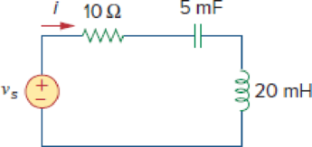
Chapter 9, Problem 35P
Find the steady-state current i in the circuit of Fig. 9.42, when vs(t) = 115 cos 200t V.
Figure 9.42
Expert Solution & Answer

Trending nowThis is a popular solution!

Students have asked these similar questions
An industrial coil is modeled as a series combination
...
of an inductance L and resistance R, as shown in
Fig. 9.90. Since an ac voltmeter measures only
the magnitude of a sinusoid, the following
measurements are taken at 60 Hz when the circuit
operates in the steady state:
80 Ω
Coil
ww
V
E
L
Decermine Rit.
E = 193 V
V1 = 67 V
Vo = 104 V
Round your answer to 4 decimal places.
all
The ac bridge shown in Fig. 9.84 is known as a
Maxwell bridge and is used for accurate measurement
of inductance and resistance of a coil in terms of a
standard capacitance C.. Show that when the bridge
is balanced,
R2 R3
R₁
Lx = R₂R3Cs and Rx
=
1.6 ΚΩ,
Find Lx and R, for R₁ = 40 kN, R₂
R3 = 4 kn, and C₂ = 0.45 µF.
R₁
R3
Cs
R₂
AC
meter
R₂
ell
An industrial coil is modeled as a series combination
...
of an inductance L and resistance R, as shown in
Fig. 9.90. Since an ac voltmeter measures only
the magnitude of a sinusoid, the following
measurements are taken at 60 Hz when the circuit
operates in the steady state:
80 Ω
Coil
ww
E
V,
Determine R if:
E = 182 V
V1 =71 V
Vo = 109 V
Round your answerto 4 decimal places.
Compute Lin millihenries based on the given parameters for the industrial coil circuit.
No label, no unit, just the number.
Chapter 9 Solutions
Fundamentals of Electric Circuits
Ch. 9.2 - Practice Problem 9.1 Given the sinusoid 45 cos(5t...Ch. 9.2 - Practice Problem 9.2 Find the phase angle between...Ch. 9.3 - Prob. 3PPCh. 9.3 - Express these sinusoids as phasors: (a)...Ch. 9.3 - Find the sinusoids corresponding to these phasors:...Ch. 9.3 - If v1=10sint30V and v2=20cost+45V, find v=v1+v2.Ch. 9.3 - Prob. 7PPCh. 9.4 - If voltage v=25sin100t15V is applied to a 50F...Ch. 9.5 - Refer to Fig. 9.17. Determine v(t) and i(t).Ch. 9.7 - Determine the input impedance of the circuit in...
Ch. 9.7 - Calculate vo in the circuit of Fig. 9.27. Figure...Ch. 9.7 - Find I in the circuit of Fig. 9.30. Figure 9.30Ch. 9.8 - Design an RC circuit to provide a 90 lagging phase...Ch. 9.8 - Refer to the RL circuit in Fig. 9.36. If 10 V is...Ch. 9.8 - In the ac bridge circuit of Fig. 9.37, suppose...Ch. 9 - Which of the following is not a right way to...Ch. 9 - A function that repeats itself after fixed...Ch. 9 - Which of these frequencies has the shorter period?...Ch. 9 - If v1 = 30 sin(t + 10) and v2 = 20 sin(t + 50),...Ch. 9 - The voltage across an inductor leads the current...Ch. 9 - The imaginary part of impedance is called:...Ch. 9 - The impedance of a capacitor increases with...Ch. 9 - At what frequency will the output voltage v0(t) in...Ch. 9 - A series RC circuit has VR = 12 V and VC = 5 V....Ch. 9 - A series RCL circuit has R = 30 , XC = 50 , and XL...Ch. 9 - Given the sinusoidal voltage v(t) = 50 cos (30t +...Ch. 9 - A current source in a linear circuit has...Ch. 9 - Express the following functions in cosine form:...Ch. 9 - Design a problem to help other students better...Ch. 9 - Given v1=45sint+30V and v2=50cost30V, determine...Ch. 9 - For the following pairs of sinusoids, determine...Ch. 9 - If f() = cos + j sin , show that f() = ej.Ch. 9 - Calculate these complex numbers and express your...Ch. 9 - Evaluate the following complex numbers and leave...Ch. 9 - Design a problem to help other students better...Ch. 9 - Find the phasors corresponding to the following...Ch. 9 - Let X=440 and Y=2030. Evaluate the following...Ch. 9 - Evaluate the following complex numbers: (a)...Ch. 9 - Simplify the following expression: (a)...Ch. 9 - Evaluate these determinants: (a) 10+j62j351+j (b)...Ch. 9 - Prob. 16PCh. 9 - Two voltages v1 and v2 appear in series so that...Ch. 9 - Obtain the sinusoids corresponding to each of the...Ch. 9 - Using phasors, find: (a) 3cos20t+105cos20t30 (b)...Ch. 9 - A linear network has a current input 7.5cos10t+30A...Ch. 9 - Simplify the following: (a) ft=5cos2t+154sin2t30...Ch. 9 - An alternating voltage is given by v(t) = 55...Ch. 9 - Apply phasor analysis to evaluate the following:...Ch. 9 - Find v(t) in the following integrodifferential...Ch. 9 - Using phasors, determine i(t) in the following...Ch. 9 - Prob. 26PCh. 9 - A parallel RLC circuit has the node equation...Ch. 9 - Determine the current that flows through an 20-...Ch. 9 - Given that vc(0) = 2 cos(155) V, what is the...Ch. 9 - A voltage v(t) = 100 cos(60t + 20) V is applied to...Ch. 9 - A series RLC circuit has R = 80 , L = 240 mH, and...Ch. 9 - Using Fig. 9.40, design a problem to help other...Ch. 9 - A series RL circuit is connected to a 220-V ac...Ch. 9 - What value of will cause the forced response, vo...Ch. 9 - Find the steady-state current i in the circuit of...Ch. 9 - Using Fig. 9.43, design a problem to help other...Ch. 9 - Determine the admittance Y for the circuit in Fig....Ch. 9 - Using Fig. 9.45, design a problem to help other...Ch. 9 - For the circuit shown in Fig. 9.46, find Zeq and...Ch. 9 - In the circuit of Fig. 9.47, find io when: (a) =...Ch. 9 - Find v(t) in the RLC circuit of Fig. 9.48. Figure...Ch. 9 - Calculate vo(t) in the circuit of Fig. 9.49....Ch. 9 - Find current Io in the circuit shown in Fig. 9.50....Ch. 9 - Calculate i(t) in the circuit of Fig. 9.51. Figure...Ch. 9 - Find current Io in the network of Fig. 9.52....Ch. 9 - If vs = 100 sin(10t + 18) V in the circuit of Fig....Ch. 9 - In the circuit of Fig. 9.54, determine the value...Ch. 9 - Given that vs(t) = 20 sin (100t 40) in Fig. 9.55,...Ch. 9 - Find vs (t) in the circuit of Fig. 9.56 if the...Ch. 9 - Determine vx in the circuit of Fig. 9.57. Let...Ch. 9 - If the voltage vo across the 2- resistor in the...Ch. 9 - If V in the circuit of Fig. 9.59, find Is. Figure...Ch. 9 - Find Io in the circuit of Fig. 9.60.Ch. 9 - In the circuit of Fig. 9.61, Find Vs if Io=300A.Ch. 9 - Find Z in the network of Fig. 9.62, given that...Ch. 9 - At = 377 rad/s, find the input impedance of the...Ch. 9 - At = 1 rad/s, obtain the input admittance in the...Ch. 9 - Using Fig. 9.65, design a problem to help other...Ch. 9 - For the network in Fig. 9.66, find Zin. Let = 100...Ch. 9 - Obtain Zin for the circuit in Fig. 9.67. Figure...Ch. 9 - Find Zeq in the circuit in Fig. 9.68. Figure 9.68Ch. 9 - For the circuit in Fig. 9.69, find the input...Ch. 9 - For the circuit in Fig. 9.70, find the value of...Ch. 9 - Find ZT and Vo in the circuit in Fig. 9.71. Let...Ch. 9 - Determine ZT and I for the circuit in Fig. 9.72....Ch. 9 - For the circuit in Fig. 9.73, calculate ZT and...Ch. 9 - At = 103 rad/s, find the input admittance of each...Ch. 9 - Determine Yeq for the circuit in Fig. 9.75. Figure...Ch. 9 - Find the equivalent admittance Yeq of the circuit...Ch. 9 - Find the equivalent impedance of the circuit in...Ch. 9 - Obtain the equivalent impedance of the circuit in...Ch. 9 - Calculate the value of Zab in the network of Fig....Ch. 9 - Determine the equivalent impedance of the circuit...Ch. 9 - Design an RL circuit to provide a 90 leading phase...Ch. 9 - Design a circuit that will transform a sinusoidal...Ch. 9 - For the following pairs of signals, determine if...Ch. 9 - Refer to the RC circuit in Fig. 9.81. (a)...Ch. 9 - A coil with impedance 8 + j6 is connected in...Ch. 9 - (a) Calculate the phase shift of the circuit in...Ch. 9 - Consider the phase-shifting circuit in Fig. 9.83....Ch. 9 - The ac bridge in Fig. 9.37 is balanced when R1 =...Ch. 9 - A capacitance bridge balances when R1 = 100 , R2 =...Ch. 9 - An inductive bridge balances when R1 = 1.2 k, R2 =...Ch. 9 - The ac bridge shown in Fig. 9.84 is known as a...Ch. 9 - The ac bridge circuit of Fig. 9.85 is called a...Ch. 9 - The circuit shown in Fig. 9.86 is used in a...Ch. 9 - The network in Fig. 9.87 is part of the schematic...Ch. 9 - A series audio circuit is shown in Fig. 9.88. (a)...Ch. 9 - An industrial load is modeled as a series...Ch. 9 - An industrial coil is modeled as a series...Ch. 9 - Figure 9.91 shows a series combination of an...Ch. 9 - A transmission line has a series impedance of and...Ch. 9 - A power transmission system is modeled as shown in...
Additional Engineering Textbook Solutions
Find more solutions based on key concepts
Analog Voltmeter Design Figure P2-98(a) shows a voltmeter circuit consisting of a D'Arsonval meter, two series ...
ANALYSIS+DESIGN OF LINEAR CIRCUITS(LL)
Explain the main function of each of the following major components of a PLC: a. Processor module (CPU) b. I/O ...
Programmable Logic Controllers
With respect to the circuit in Fig. 5.90, (a) employ Thévenin’s theorem to determine the equivalent network see...
Loose Leaf for Engineering Circuit Analysis Format: Loose-leaf
Design an ideal inverting op-amp circuit such that the voltage gain is Av=25 . The maximum current in any resis...
Microelectronics: Circuit Analysis and Design
A constant voltage of 10V is applied to a 50H inductance, as shown in Figure P3.51 Figure P3 51 The current in ...
Electrical Engineering: Principles & Applications (7th Edition)
Identify the type of input and output configuration for each diff-amp in Figure 18-35.
Electronics Fundamentals: Circuits, Devices & Applications
Knowledge Booster


Learn more about
Need a deep-dive on the concept behind this application? Look no further. Learn more about this topic, electrical-engineering and related others by exploring similar questions and additional content below.Similar questions
- In the circuit shown in Figure, the switch S is closed at time t = 0. the voltage across the inductance at t = 0+ 3.02 10V A) 2V B 4V c) -6V D) 8V S 4F 402 HIMM WWW 49 ellarrow_forwardConsider a sinusoidal emf source, v(t) = Vm sin (@t) results of current of i(t) = Im sin (@t+0) is applied to circuit of R, L & C in series. How to find the voltage across each one?.arrow_forwardThe voltage and current of an element are i(t) = 3.cos(1000t + 10°) V(t) = 6.cos(1000t – 80°) The element is Select one: a. resistor and capacitor (R and C) b. resistor R c. Inductor L d. Capacitor Carrow_forward
- An inductor having an impedance of 6 + j8 is connected across a 200v supply. The real power supplied to it is watts. choices: 4000 3200 2400 1200arrow_forwardI am trouble understanding this circuit. Here, R= 25.0 ohms, L=30.0 mH and C=12.0µF. Additionally the amplitude and frequency of the source voltage are 20.0 V, and 500 Hz. a) I would like to find the impedance for the circuit and the amplitude of current. b) I would like to find the amplitude f voltage across the resistor, inductor, and capactitor. Any help and guidence would be greatly appreciated :)arrow_forward9. Recall that Kirchhoff's laws help to get the current in circuits. Consider the following circuit: L R I(t) C +q(t) -q(t) Ignore the alternating power for this problem. a) What is the voltage over the resistor if it has a resistance of R ohms and the current is I ampere? b) What is the voltage over the capacitor if the capacitance is C and the charge on the capacitor is q. c) What is the voltage over the inductor if it has an inductance of L Henry? The answer must be in a form of a differential equation.arrow_forward
- A voltage v(t) = 100 cos(60t + 20°) V is applied to a parallel combination of a 40-k resistor and a 50-μF capacitor. Find the steady-state currents through the resistor and the capacitor.arrow_forwardThe circuit in figure 1 is operating in the sinusoidal steady state. Find the steady state response Vx(1) C1 HH 2uF Icos(25001) A R2 2000 R1: 2000 Figure 1arrow_forwardProblem 9.82 Figure 50:1 JINI. Ideal Z be 1:20 Ideal ZL 1 of 1 Part A Find the impedance Zab in the circuit in (Figure 1) if Z=200/- 55° 2. Enter your answer using polar notation. Express argument in degrees. Zab= VAΣ vec Submit xa xb b √x √√x 1x1 T20 (X)* < Return to Assignment You have already submitted this answer. Enter a new answer. No credit lost. Try again. Previous Answers Request Answer Provide Feedback X.10n X ? Ωarrow_forward
- A circuit is designed with an AC source of max voltage 12 and frequency 60 Hz. The circuit has a resistance of 1050 Ohms, an inductance of 0.06 Henrys, and a capacitance of 0.009 coulombs per volt. - omega for source in rad/s? - omegaR for circuit? -XL? -XC? -phi in radians? -Z? -imax?arrow_forwardAC circuits pQ Figure 9.30 For Practice Prob. 9.12. Find 1 in the circuit of Fig. 9.30. Answer: 9.546/33.8° A.arrow_forwardGiven That: Is=0.0098, R1=60000, R2=6000 0, L=16 H, C=2 F, The circuit shown below under dc conditions find the following: L ell Is R1 R2 the current in L The voltage across capacitorarrow_forward
arrow_back_ios
SEE MORE QUESTIONS
arrow_forward_ios
Recommended textbooks for you
 Introductory Circuit Analysis (13th Edition)Electrical EngineeringISBN:9780133923605Author:Robert L. BoylestadPublisher:PEARSON
 Delmar's Standard Textbook Of ElectricityElectrical EngineeringISBN:9781337900348Author:Stephen L. HermanPublisher:Cengage Learning
 Programmable Logic ControllersElectrical EngineeringISBN:9780073373843Author:Frank D. PetruzellaPublisher:McGraw-Hill Education
 Fundamentals of Electric CircuitsElectrical EngineeringISBN:9780078028229Author:Charles K Alexander, Matthew SadikuPublisher:McGraw-Hill Education
 Electric Circuits. (11th Edition)Electrical EngineeringISBN:9780134746968Author:James W. Nilsson, Susan RiedelPublisher:PEARSON
 Engineering ElectromagneticsElectrical EngineeringISBN:9780078028151Author:Hayt, William H. (william Hart), Jr, BUCK, John A.Publisher:Mcgraw-hill Education,
Introductory Circuit Analysis (13th Edition)
Electrical Engineering
ISBN:9780133923605
Author:Robert L. Boylestad
Publisher:PEARSON
Delmar's Standard Textbook Of Electricity
Electrical Engineering
ISBN:9781337900348
Author:Stephen L. Herman
Publisher:Cengage Learning
Programmable Logic Controllers
Electrical Engineering
ISBN:9780073373843
Author:Frank D. Petruzella
Publisher:McGraw-Hill Education
Fundamentals of Electric Circuits
Electrical Engineering
ISBN:9780078028229
Author:Charles K Alexander, Matthew Sadiku
Publisher:McGraw-Hill Education
Electric Circuits. (11th Edition)
Electrical Engineering
ISBN:9780134746968
Author:James W. Nilsson, Susan Riedel
Publisher:PEARSON
Engineering Electromagnetics
Electrical Engineering
ISBN:9780078028151
Author:Hayt, William H. (william Hart), Jr, BUCK, John A.
Publisher:Mcgraw-hill Education,
ENA 9.2(1)(En)(Alex) Sinusoids & Phasors - Explanation with Example 9.1 ,9.2 & PP 9.2; Author: Electrical Engineering Academy;https://www.youtube.com/watch?v=vX_LLNl-ZpU;License: Standard YouTube License, CC-BY
Electrical Engineering: Ch 10 Alternating Voltages & Phasors (8 of 82) What is a Phasor?; Author: Michel van Biezen;https://www.youtube.com/watch?v=2I1tF3ixNg0;License: Standard Youtube License