
Fundamentals of Electric Circuits
6th Edition
ISBN: 9780078028229
Author: Charles K Alexander, Matthew Sadiku
Publisher: McGraw-Hill Education
expand_more
expand_more
format_list_bulleted
Videos
Textbook Question
Chapter 9, Problem 57P
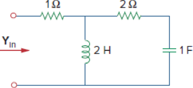
At ω = 1 rad/s, obtain the input admittance in the circuit of Fig. 9.64.
Figure 9.64
Expert Solution & Answer
Want to see the full answer?
Check out a sample textbook solution
Students have asked these similar questions
For the following circuit, use phasor-impedance techniques to find the current through the
inductor
6 cos 2t A
0.5 H
10 H
1/2 F
592
www
THE
Use Euler's formula to simplify:
cos(1+i).
..
Compute the effective value of current.
9 TIP: Use your CASIO's INTEGRATE function.
i(t) A
...
a
T/2
b
a = 13 A
b = -15 A
T= 4 s
Chapter 9 Solutions
Fundamentals of Electric Circuits
Ch. 9.2 - Practice Problem 9.1 Given the sinusoid 45 cos(5t...Ch. 9.2 - Practice Problem 9.2 Find the phase angle between...Ch. 9.3 - Prob. 3PPCh. 9.3 - Express these sinusoids as phasors: (a)...Ch. 9.3 - Find the sinusoids corresponding to these phasors:...Ch. 9.3 - If v1=10sint30V and v2=20cost+45V, find v=v1+v2.Ch. 9.3 - Prob. 7PPCh. 9.4 - If voltage v=25sin100t15V is applied to a 50F...Ch. 9.5 - Refer to Fig. 9.17. Determine v(t) and i(t).Ch. 9.7 - Determine the input impedance of the circuit in...
Ch. 9.7 - Calculate vo in the circuit of Fig. 9.27. Figure...Ch. 9.7 - Find I in the circuit of Fig. 9.30. Figure 9.30Ch. 9.8 - Design an RC circuit to provide a 90 lagging phase...Ch. 9.8 - Refer to the RL circuit in Fig. 9.36. If 10 V is...Ch. 9.8 - In the ac bridge circuit of Fig. 9.37, suppose...Ch. 9 - Which of the following is not a right way to...Ch. 9 - A function that repeats itself after fixed...Ch. 9 - Which of these frequencies has the shorter period?...Ch. 9 - If v1 = 30 sin(t + 10) and v2 = 20 sin(t + 50),...Ch. 9 - The voltage across an inductor leads the current...Ch. 9 - The imaginary part of impedance is called:...Ch. 9 - The impedance of a capacitor increases with...Ch. 9 - At what frequency will the output voltage v0(t) in...Ch. 9 - A series RC circuit has VR = 12 V and VC = 5 V....Ch. 9 - A series RCL circuit has R = 30 , XC = 50 , and XL...Ch. 9 - Given the sinusoidal voltage v(t) = 50 cos (30t +...Ch. 9 - A current source in a linear circuit has...Ch. 9 - Express the following functions in cosine form:...Ch. 9 - Design a problem to help other students better...Ch. 9 - Given v1=45sint+30V and v2=50cost30V, determine...Ch. 9 - For the following pairs of sinusoids, determine...Ch. 9 - If f() = cos + j sin , show that f() = ej.Ch. 9 - Calculate these complex numbers and express your...Ch. 9 - Evaluate the following complex numbers and leave...Ch. 9 - Design a problem to help other students better...Ch. 9 - Find the phasors corresponding to the following...Ch. 9 - Let X=440 and Y=2030. Evaluate the following...Ch. 9 - Evaluate the following complex numbers: (a)...Ch. 9 - Simplify the following expression: (a)...Ch. 9 - Evaluate these determinants: (a) 10+j62j351+j (b)...Ch. 9 - Prob. 16PCh. 9 - Two voltages v1 and v2 appear in series so that...Ch. 9 - Obtain the sinusoids corresponding to each of the...Ch. 9 - Using phasors, find: (a) 3cos20t+105cos20t30 (b)...Ch. 9 - A linear network has a current input 7.5cos10t+30A...Ch. 9 - Simplify the following: (a) ft=5cos2t+154sin2t30...Ch. 9 - An alternating voltage is given by v(t) = 55...Ch. 9 - Apply phasor analysis to evaluate the following:...Ch. 9 - Find v(t) in the following integrodifferential...Ch. 9 - Using phasors, determine i(t) in the following...Ch. 9 - Prob. 26PCh. 9 - A parallel RLC circuit has the node equation...Ch. 9 - Determine the current that flows through an 20-...Ch. 9 - Given that vc(0) = 2 cos(155) V, what is the...Ch. 9 - A voltage v(t) = 100 cos(60t + 20) V is applied to...Ch. 9 - A series RLC circuit has R = 80 , L = 240 mH, and...Ch. 9 - Using Fig. 9.40, design a problem to help other...Ch. 9 - A series RL circuit is connected to a 220-V ac...Ch. 9 - What value of will cause the forced response, vo...Ch. 9 - Find the steady-state current i in the circuit of...Ch. 9 - Using Fig. 9.43, design a problem to help other...Ch. 9 - Determine the admittance Y for the circuit in Fig....Ch. 9 - Using Fig. 9.45, design a problem to help other...Ch. 9 - For the circuit shown in Fig. 9.46, find Zeq and...Ch. 9 - In the circuit of Fig. 9.47, find io when: (a) =...Ch. 9 - Find v(t) in the RLC circuit of Fig. 9.48. Figure...Ch. 9 - Calculate vo(t) in the circuit of Fig. 9.49....Ch. 9 - Find current Io in the circuit shown in Fig. 9.50....Ch. 9 - Calculate i(t) in the circuit of Fig. 9.51. Figure...Ch. 9 - Find current Io in the network of Fig. 9.52....Ch. 9 - If vs = 100 sin(10t + 18) V in the circuit of Fig....Ch. 9 - In the circuit of Fig. 9.54, determine the value...Ch. 9 - Given that vs(t) = 20 sin (100t 40) in Fig. 9.55,...Ch. 9 - Find vs (t) in the circuit of Fig. 9.56 if the...Ch. 9 - Determine vx in the circuit of Fig. 9.57. Let...Ch. 9 - If the voltage vo across the 2- resistor in the...Ch. 9 - If V in the circuit of Fig. 9.59, find Is. Figure...Ch. 9 - Find Io in the circuit of Fig. 9.60.Ch. 9 - In the circuit of Fig. 9.61, Find Vs if Io=300A.Ch. 9 - Find Z in the network of Fig. 9.62, given that...Ch. 9 - At = 377 rad/s, find the input impedance of the...Ch. 9 - At = 1 rad/s, obtain the input admittance in the...Ch. 9 - Using Fig. 9.65, design a problem to help other...Ch. 9 - For the network in Fig. 9.66, find Zin. Let = 100...Ch. 9 - Obtain Zin for the circuit in Fig. 9.67. Figure...Ch. 9 - Find Zeq in the circuit in Fig. 9.68. Figure 9.68Ch. 9 - For the circuit in Fig. 9.69, find the input...Ch. 9 - For the circuit in Fig. 9.70, find the value of...Ch. 9 - Find ZT and Vo in the circuit in Fig. 9.71. Let...Ch. 9 - Determine ZT and I for the circuit in Fig. 9.72....Ch. 9 - For the circuit in Fig. 9.73, calculate ZT and...Ch. 9 - At = 103 rad/s, find the input admittance of each...Ch. 9 - Determine Yeq for the circuit in Fig. 9.75. Figure...Ch. 9 - Find the equivalent admittance Yeq of the circuit...Ch. 9 - Find the equivalent impedance of the circuit in...Ch. 9 - Obtain the equivalent impedance of the circuit in...Ch. 9 - Calculate the value of Zab in the network of Fig....Ch. 9 - Determine the equivalent impedance of the circuit...Ch. 9 - Design an RL circuit to provide a 90 leading phase...Ch. 9 - Design a circuit that will transform a sinusoidal...Ch. 9 - For the following pairs of signals, determine if...Ch. 9 - Refer to the RC circuit in Fig. 9.81. (a)...Ch. 9 - A coil with impedance 8 + j6 is connected in...Ch. 9 - (a) Calculate the phase shift of the circuit in...Ch. 9 - Consider the phase-shifting circuit in Fig. 9.83....Ch. 9 - The ac bridge in Fig. 9.37 is balanced when R1 =...Ch. 9 - A capacitance bridge balances when R1 = 100 , R2 =...Ch. 9 - An inductive bridge balances when R1 = 1.2 k, R2 =...Ch. 9 - The ac bridge shown in Fig. 9.84 is known as a...Ch. 9 - The ac bridge circuit of Fig. 9.85 is called a...Ch. 9 - The circuit shown in Fig. 9.86 is used in a...Ch. 9 - The network in Fig. 9.87 is part of the schematic...Ch. 9 - A series audio circuit is shown in Fig. 9.88. (a)...Ch. 9 - An industrial load is modeled as a series...Ch. 9 - An industrial coil is modeled as a series...Ch. 9 - Figure 9.91 shows a series combination of an...Ch. 9 - A transmission line has a series impedance of and...Ch. 9 - A power transmission system is modeled as shown in...
Knowledge Booster


Learn more about
Need a deep-dive on the concept behind this application? Look no further. Learn more about this topic, electrical-engineering and related others by exploring similar questions and additional content below.Similar questions
- A coil with impedance 8 + j6 is connected in series with a capacitive reactance X. The series combination is connected in parallel with a resistor R. Given that the equivalent impedance of the resulting circuit is 2 ≤ 0° №, find the value of R and X. The value of R= Q and X= Ω.arrow_forwardI VY O non-sinusoidal... -> For the circuit shown below calculate the output voltage Vo(t). v(t)=cos(t)+2cos (2t)arrow_forwardLet Zeq be the equivalent impedance of a parallel connection of an inductor with inductance L and a capacitor with capacitance C. At w=1/√√LC, the equivalent impedance is given by O a. Zeq = 0 b. Zeq = 1 O c. Zeq = 00 O d. Zeq = 0.5arrow_forward
- Select all correct statement(s):1, The equivalent resistance for resistors in parallel is the harmonic mean of all resistors;2, The equivalent capacitance for capacitors in series is the sum of all capacitors;3, The equivalent inductance for inductors in series is the sum of all resistors.32None of them is correct1arrow_forwardTutorial exercise Jimmy the Circuit Builder is at it again and this time he is using AC. He has all of the linear components in pairs: two AC voltage sources, two AC current sources, two resistors, two capacitors and two inductors. He is trying to build circuits to create certain voltages and currents. All of the sources operate at w=500 rad/s. 940° V 2 <90° A - 12<60° V 1-30° A (c) V=6490° V (d) I=64150° A (e) I = 0.6 +j1.04 (f) V=18.25434.7° V + (a) Draw the circuit. (b) Calculate the voltage across each component. 100μF TE 1mF 46 392 -M 1mH hint: try combining the two sources 10mH Jimmy first builds one circuit to check his understanding of AC voltage, current and power. The circuit is a series connection of the 12 <60° V voltage source, the 3 resistor, the 10 mH inductor, and the 1mF capacitor. 1092 M Using only two elements, connect the pair of elements to create the following AC voltage and currents: Using exactly three elements, draw circuits to create the following AC voltage…arrow_forwardThe current in an L-R-C series circuit has amplitude 0.120 Aand angular frequency 8.00 * 103 rad/s, and it has its maximum positivevalue at t = 0. The resistance is 95.0 Ω, the inductance is 6.50 mH,and the capacitance is 0.440 mF. For the resistor, inductor, and capacitor,find (a) the voltage amplitudes and (b) the instantaneous voltages att = 0.305 ms.arrow_forward
- A 116 Ω resistor and an unknown capacitor are connectedin series to an ac source with angular frequency 5.10 * 10^3 rad/s. Theamplitude of the resistor voltage is 2.45 V, and the current in the circuithas its maximum positive value at t = 0. Find the capacitancearrow_forwardA radio tuning circuit contains an RLC circuit with R = 25.0 ohms and C=4.40*10^ -12 F. and an ac generator with an rms voltage of 220 V which is applied at a frequency of f = 2.30 * 10 ^ 8 Hz. (a) What inductance(s) needs to be attached in series to this circuit so that the rms current is 2.30 A? (b) Find the power factor for this circuit. (c) In order to increase the power factor to 0.770, the inductor(s) from part (a) is replaced with a different inductor(s). Find the required value(s) of the new inductor.arrow_forwardThe Norton equivalent of a circuit is characterized by ZN = 100Đ45° W, and In = 2.4Đ-15° A. Determine the Thévenin equivalent in terms of ZTh and ETh. ZTh = 41.7Đ45° W, VTh = 24Đ0° V ZTh = 100Đ45° W, VTh = 240Ð30° V %3D ZTh = 100Đ-45° W, VTh = 24OĐ60° V %3D ZTh = 63.8Đ55° W, VTh = 41.7Đ60° Varrow_forward
- What capacitance is needed and the construction of the circuit if you need to filter AC signals above 2 kHz with a 16 Ω load? Present your circuit diagram with a solution by typing it in the field below or by attaching a photo of your calculations to supplement your provided diagram.arrow_forwardA series RLC circuit containing a resistance of 15Ω, an inductance of 0.2H and a capacitor of 150uF are connected in series across a 100Vrms, 50Hz supply a. Calculate the total circuit impedance (Z), the circuits current (Is), voltages across the series rlc circuit (VR, VL, VC) power factor (cosθ) and phase angle (θ) and draw the voltage phasor diagram.arrow_forwardQues 2 An RLC series circuit has R = 502, C = 50µF and a variable inductance. The applied voltage is 220 V at 100 rad/sec. The inductance is varied till the voltage across resistance is maximum. Under this condition, find the (i). Value of inductance (ii) Q - Factorarrow_forward
arrow_back_ios
SEE MORE QUESTIONS
arrow_forward_ios
Recommended textbooks for you
 Delmar's Standard Textbook Of ElectricityElectrical EngineeringISBN:9781337900348Author:Stephen L. HermanPublisher:Cengage Learning
Delmar's Standard Textbook Of Electricity
Electrical Engineering
ISBN:9781337900348
Author:Stephen L. Herman
Publisher:Cengage Learning
02 - Sinusoidal AC Voltage Sources in Circuits, Part 1; Author: Math and Science;https://www.youtube.com/watch?v=8zMiIHVMfaw;License: Standard Youtube License