
Fundamentals of Electric Circuits
6th Edition
ISBN: 9780078028229
Author: Charles K Alexander, Matthew Sadiku
Publisher: McGraw-Hill Education
expand_more
expand_more
format_list_bulleted
Videos
Textbook Question
Chapter 9, Problem 39P
For the circuit shown in Fig. 9.46, find Zeq and use that to find current I. Let ω = 10 rad/s.
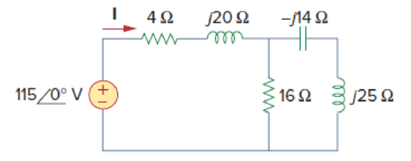
Figure 9.46
Expert Solution & Answer
Want to see the full answer?
Check out a sample textbook solution
Students have asked these similar questions
Tutorial exercise
Jimmy the Circuit Builder is at it again and this time he is using AC. He has all of the linear
components in pairs: two AC voltage sources, two AC current sources, two resistors, two
capacitors and two inductors. He is trying to build circuits to create certain voltages and
currents. All of the sources operate at w=500 rad/s.
940° V
2 <90° A
-
12<60° V
1-30° A
(c) V=6490° V
(d) I=64150° A
(e) I = 0.6 +j1.04
(f) V=18.25434.7° V
+
(a) Draw the circuit.
(b) Calculate the voltage across each component.
100μF
TE
1mF
46
392
-M
1mH
hint: try combining the two sources
10mH
Jimmy first builds one circuit to check his understanding of AC voltage, current and power. The
circuit is a series connection of the 12 <60° V voltage source, the 3 resistor, the 10 mH inductor,
and the 1mF capacitor.
1092
M
Using only two elements, connect the pair of elements to create the following AC voltage and
currents:
Using exactly three elements, draw circuits to create the following AC voltage…
The voltage applied to a circuit is:
v = 215 sin (377t)- 140 (cos 754t) +70 sin (1131t)
And the current in the circuit is:
i= 15 cos (377t -30°) + 4 cos (754t-60°) + 3 sin (1131t+50°)
What will be the fundamental frequency
Let Zeq be the equivalent impedance of a series connection of an
inductor with inductance L and a capacitor with capacitance C. At
w=1/√√LC, the equivalent impedance is given by _
O
a. Zeq = 00
O b. Zeq = 0
O c. Zeq = 0.5
O
d. Zeq = 1
Chapter 9 Solutions
Fundamentals of Electric Circuits
Ch. 9.2 - Practice Problem 9.1 Given the sinusoid 45 cos(5t...Ch. 9.2 - Practice Problem 9.2 Find the phase angle between...Ch. 9.3 - Prob. 3PPCh. 9.3 - Express these sinusoids as phasors: (a)...Ch. 9.3 - Find the sinusoids corresponding to these phasors:...Ch. 9.3 - If v1=10sint30V and v2=20cost+45V, find v=v1+v2.Ch. 9.3 - Prob. 7PPCh. 9.4 - If voltage v=25sin100t15V is applied to a 50F...Ch. 9.5 - Refer to Fig. 9.17. Determine v(t) and i(t).Ch. 9.7 - Determine the input impedance of the circuit in...
Ch. 9.7 - Calculate vo in the circuit of Fig. 9.27. Figure...Ch. 9.7 - Find I in the circuit of Fig. 9.30. Figure 9.30Ch. 9.8 - Design an RC circuit to provide a 90 lagging phase...Ch. 9.8 - Refer to the RL circuit in Fig. 9.36. If 10 V is...Ch. 9.8 - In the ac bridge circuit of Fig. 9.37, suppose...Ch. 9 - Which of the following is not a right way to...Ch. 9 - A function that repeats itself after fixed...Ch. 9 - Which of these frequencies has the shorter period?...Ch. 9 - If v1 = 30 sin(t + 10) and v2 = 20 sin(t + 50),...Ch. 9 - The voltage across an inductor leads the current...Ch. 9 - The imaginary part of impedance is called:...Ch. 9 - The impedance of a capacitor increases with...Ch. 9 - At what frequency will the output voltage v0(t) in...Ch. 9 - A series RC circuit has VR = 12 V and VC = 5 V....Ch. 9 - A series RCL circuit has R = 30 , XC = 50 , and XL...Ch. 9 - Given the sinusoidal voltage v(t) = 50 cos (30t +...Ch. 9 - A current source in a linear circuit has...Ch. 9 - Express the following functions in cosine form:...Ch. 9 - Design a problem to help other students better...Ch. 9 - Given v1=45sint+30V and v2=50cost30V, determine...Ch. 9 - For the following pairs of sinusoids, determine...Ch. 9 - If f() = cos + j sin , show that f() = ej.Ch. 9 - Calculate these complex numbers and express your...Ch. 9 - Evaluate the following complex numbers and leave...Ch. 9 - Design a problem to help other students better...Ch. 9 - Find the phasors corresponding to the following...Ch. 9 - Let X=440 and Y=2030. Evaluate the following...Ch. 9 - Evaluate the following complex numbers: (a)...Ch. 9 - Simplify the following expression: (a)...Ch. 9 - Evaluate these determinants: (a) 10+j62j351+j (b)...Ch. 9 - Prob. 16PCh. 9 - Two voltages v1 and v2 appear in series so that...Ch. 9 - Obtain the sinusoids corresponding to each of the...Ch. 9 - Using phasors, find: (a) 3cos20t+105cos20t30 (b)...Ch. 9 - A linear network has a current input 7.5cos10t+30A...Ch. 9 - Simplify the following: (a) ft=5cos2t+154sin2t30...Ch. 9 - An alternating voltage is given by v(t) = 55...Ch. 9 - Apply phasor analysis to evaluate the following:...Ch. 9 - Find v(t) in the following integrodifferential...Ch. 9 - Using phasors, determine i(t) in the following...Ch. 9 - Prob. 26PCh. 9 - A parallel RLC circuit has the node equation...Ch. 9 - Determine the current that flows through an 20-...Ch. 9 - Given that vc(0) = 2 cos(155) V, what is the...Ch. 9 - A voltage v(t) = 100 cos(60t + 20) V is applied to...Ch. 9 - A series RLC circuit has R = 80 , L = 240 mH, and...Ch. 9 - Using Fig. 9.40, design a problem to help other...Ch. 9 - A series RL circuit is connected to a 220-V ac...Ch. 9 - What value of will cause the forced response, vo...Ch. 9 - Find the steady-state current i in the circuit of...Ch. 9 - Using Fig. 9.43, design a problem to help other...Ch. 9 - Determine the admittance Y for the circuit in Fig....Ch. 9 - Using Fig. 9.45, design a problem to help other...Ch. 9 - For the circuit shown in Fig. 9.46, find Zeq and...Ch. 9 - In the circuit of Fig. 9.47, find io when: (a) =...Ch. 9 - Find v(t) in the RLC circuit of Fig. 9.48. Figure...Ch. 9 - Calculate vo(t) in the circuit of Fig. 9.49....Ch. 9 - Find current Io in the circuit shown in Fig. 9.50....Ch. 9 - Calculate i(t) in the circuit of Fig. 9.51. Figure...Ch. 9 - Find current Io in the network of Fig. 9.52....Ch. 9 - If vs = 100 sin(10t + 18) V in the circuit of Fig....Ch. 9 - In the circuit of Fig. 9.54, determine the value...Ch. 9 - Given that vs(t) = 20 sin (100t 40) in Fig. 9.55,...Ch. 9 - Find vs (t) in the circuit of Fig. 9.56 if the...Ch. 9 - Determine vx in the circuit of Fig. 9.57. Let...Ch. 9 - If the voltage vo across the 2- resistor in the...Ch. 9 - If V in the circuit of Fig. 9.59, find Is. Figure...Ch. 9 - Find Io in the circuit of Fig. 9.60.Ch. 9 - In the circuit of Fig. 9.61, Find Vs if Io=300A.Ch. 9 - Find Z in the network of Fig. 9.62, given that...Ch. 9 - At = 377 rad/s, find the input impedance of the...Ch. 9 - At = 1 rad/s, obtain the input admittance in the...Ch. 9 - Using Fig. 9.65, design a problem to help other...Ch. 9 - For the network in Fig. 9.66, find Zin. Let = 100...Ch. 9 - Obtain Zin for the circuit in Fig. 9.67. Figure...Ch. 9 - Find Zeq in the circuit in Fig. 9.68. Figure 9.68Ch. 9 - For the circuit in Fig. 9.69, find the input...Ch. 9 - For the circuit in Fig. 9.70, find the value of...Ch. 9 - Find ZT and Vo in the circuit in Fig. 9.71. Let...Ch. 9 - Determine ZT and I for the circuit in Fig. 9.72....Ch. 9 - For the circuit in Fig. 9.73, calculate ZT and...Ch. 9 - At = 103 rad/s, find the input admittance of each...Ch. 9 - Determine Yeq for the circuit in Fig. 9.75. Figure...Ch. 9 - Find the equivalent admittance Yeq of the circuit...Ch. 9 - Find the equivalent impedance of the circuit in...Ch. 9 - Obtain the equivalent impedance of the circuit in...Ch. 9 - Calculate the value of Zab in the network of Fig....Ch. 9 - Determine the equivalent impedance of the circuit...Ch. 9 - Design an RL circuit to provide a 90 leading phase...Ch. 9 - Design a circuit that will transform a sinusoidal...Ch. 9 - For the following pairs of signals, determine if...Ch. 9 - Refer to the RC circuit in Fig. 9.81. (a)...Ch. 9 - A coil with impedance 8 + j6 is connected in...Ch. 9 - (a) Calculate the phase shift of the circuit in...Ch. 9 - Consider the phase-shifting circuit in Fig. 9.83....Ch. 9 - The ac bridge in Fig. 9.37 is balanced when R1 =...Ch. 9 - A capacitance bridge balances when R1 = 100 , R2 =...Ch. 9 - An inductive bridge balances when R1 = 1.2 k, R2 =...Ch. 9 - The ac bridge shown in Fig. 9.84 is known as a...Ch. 9 - The ac bridge circuit of Fig. 9.85 is called a...Ch. 9 - The circuit shown in Fig. 9.86 is used in a...Ch. 9 - The network in Fig. 9.87 is part of the schematic...Ch. 9 - A series audio circuit is shown in Fig. 9.88. (a)...Ch. 9 - An industrial load is modeled as a series...Ch. 9 - An industrial coil is modeled as a series...Ch. 9 - Figure 9.91 shows a series combination of an...Ch. 9 - A transmission line has a series impedance of and...Ch. 9 - A power transmission system is modeled as shown in...
Additional Engineering Textbook Solutions
Find more solutions based on key concepts
Three point charges of equal magnitude q, that will yield a zero net electric field at the origin.
Engineering Electromagnetics
With respect to the circuit in Fig. 5.90, (a) employ Thévenin’s theorem to determine the equivalent network see...
Loose Leaf for Engineering Circuit Analysis Format: Loose-leaf
Write the nodal equations for the network of Fig. 8.137 using the general approach. Find the nodal voltages usi...
Introductory Circuit Analysis (13th Edition)
Identify the type of input and output configuration for each diff-amp in Figure 18-35.
Electronics Fundamentals: Circuits, Devices & Applications
The current source in the circuit shown generates the current pulse
Find (a) v (0); (b) the instant of time gr...
Electric Circuits. (11th Edition)
Does the severity of an electric shock increase ordecrease with eh of the following changes? a. A decrease in t...
Electric Motors and Control Systems
Knowledge Booster


Learn more about
Need a deep-dive on the concept behind this application? Look no further. Learn more about this topic, electrical-engineering and related others by exploring similar questions and additional content below.Similar questions
- A given impedance draws 5 A from a 120 V, 60 Hz source. The current through the impedance lags the voltage across it by 60°. What is the total current drawn from the source when 100 µF capacitor is connected in parallel with the given impedance?arrow_forwardThe frequency of the voltage given by the equation e=120 sin754t is: O a) 377n O b) 340/w O c) 754 Hz O d) 120 Hzarrow_forwardSelect all correct statement(s):1, The equivalent resistance for resistors in parallel is the harmonic mean of all resistors;2, The equivalent capacitance for capacitors in series is the sum of all capacitors;3, The equivalent inductance for inductors in series is the sum of all resistors.32None of them is correct1arrow_forward
- Determine the cut-off frequency of the given network below with the given parameters. Cs= 20µF Ce=30µF Cc=2µF Rc= 10ko RL= 25KQ B=100 R1= 50KQ R2= 10kQ Re= 5kQ ro=40Qre =500 Vcc= 20V Vcc Rc R Cc C, RL FIG. 9.25arrow_forwardPower factor 90 to 100% 88 to <90% 85 to <88% 80 to <85% 75 to < 80% 70 to < 75% 65 to < 70% 60 to < 65% 55 to <60% 50 to <55% Less than 50% Surcharge None 2% 4% 9% 16% 24% 34% 44% 57% 72% 80% Use the table given for the following. a. What is the effective impedance? What is the average current drawn? What will be the surcharge? b. c. If a house with inductive loads has an avg consumption of 40kW and 26kVAR is supplied 230 Vrms source.arrow_forwardDetermine if each statement is True or False; if false, please explain whya) A forced oscillator is when a system is being yelled at to perform a specific motion.b) Impedance is a measure of the total resistance a RLC series circuit has towards current.c) The phase angle tells us how “out-of-phase” the charge on the capacitor iswith the driving voltage.arrow_forward
- Vmax=100Volt f=1000Hz f=200Hz f=330Hz m 30mH ww 200ohm 33mH 100uF m XL www 330 Ohm HH 47uF Q8: A: Find the impedance values for the following circuits:arrow_forwardFind the impedance of a series connection resistor and an inductor.the inductance is L=1mH.the resistance is R=1kohm and the angular frequency is 2.10^5rad/secarrow_forwardA series RC with R = 91-Ω and C =7-F connected across a 100 VDC source for a LONG TIME, what is the voltage across the capacitor? Write the values only (round to four decimal places).arrow_forward
- 3. At what radial frequency will this circuit have an impedance at terminals a and b that is entirely real? a 502 Z3 0.02 F Z4 0.1 H barrow_forwardA 200 Ω resistor is in series with a 1 mH inductor. Determine the impedance of this combination at 200 Hz.arrow_forwardAn inductor with L = 150mH and r = 200(Omega) is in series with a capacitor, a resistor, and a generator of w = 1000 rad / s The voltage across the inductor Vind is measured to be 10.87 V, VR is measured to be 4.65 , and Vc is measured to be 5.96 V. What is the generator voltage V? (Hint: This is the measurement to be performed in this laboratory for LCR circuits. Use the appropriate equations to find VL and Vr' and then use them and the values of VR and VC to calculate V.)arrow_forward
arrow_back_ios
SEE MORE QUESTIONS
arrow_forward_ios
Recommended textbooks for you
 Introductory Circuit Analysis (13th Edition)Electrical EngineeringISBN:9780133923605Author:Robert L. BoylestadPublisher:PEARSON
 Delmar's Standard Textbook Of ElectricityElectrical EngineeringISBN:9781337900348Author:Stephen L. HermanPublisher:Cengage Learning
 Programmable Logic ControllersElectrical EngineeringISBN:9780073373843Author:Frank D. PetruzellaPublisher:McGraw-Hill Education
 Fundamentals of Electric CircuitsElectrical EngineeringISBN:9780078028229Author:Charles K Alexander, Matthew SadikuPublisher:McGraw-Hill Education
 Electric Circuits. (11th Edition)Electrical EngineeringISBN:9780134746968Author:James W. Nilsson, Susan RiedelPublisher:PEARSON
 Engineering ElectromagneticsElectrical EngineeringISBN:9780078028151Author:Hayt, William H. (william Hart), Jr, BUCK, John A.Publisher:Mcgraw-hill Education,
Introductory Circuit Analysis (13th Edition)
Electrical Engineering
ISBN:9780133923605
Author:Robert L. Boylestad
Publisher:PEARSON
Delmar's Standard Textbook Of Electricity
Electrical Engineering
ISBN:9781337900348
Author:Stephen L. Herman
Publisher:Cengage Learning
Programmable Logic Controllers
Electrical Engineering
ISBN:9780073373843
Author:Frank D. Petruzella
Publisher:McGraw-Hill Education
Fundamentals of Electric Circuits
Electrical Engineering
ISBN:9780078028229
Author:Charles K Alexander, Matthew Sadiku
Publisher:McGraw-Hill Education
Electric Circuits. (11th Edition)
Electrical Engineering
ISBN:9780134746968
Author:James W. Nilsson, Susan Riedel
Publisher:PEARSON
Engineering Electromagnetics
Electrical Engineering
ISBN:9780078028151
Author:Hayt, William H. (william Hart), Jr, BUCK, John A.
Publisher:Mcgraw-hill Education,
Y Parameters - Admittance Parameters; Author: Electrical Engineering Authority;https://www.youtube.com/watch?v=MLqqa8YbVrA;License: Standard Youtube License