
Electronics Fundamentals: Circuits, Devices & Applications
8th Edition
ISBN: 9780135072950
Author: Thomas L. Floyd, David Buchla
Publisher: Prentice Hall
expand_more
expand_more
format_list_bulleted
Concept explainers
Videos
Textbook Question
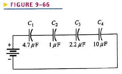
Chapter 9, Problem 21P
The total charge stored by the series capacitors in Figure 9-66 is
Determine the voltage across each of the capacitors.
Expert Solution & Answer
Want to see the full answer?
Check out a sample textbook solution
Students have asked these similar questions
I am having trouble with this problem it might be the dot notation for the inductors but I am not entierly sure that is the only issue I am having
Problem:
25 mH
m
Find Leq In below figure.
10 mH
m
60 mH
m
20 mH
m
30 mH
m
-o b
L
0000
Two series capacitors C1 and C2 are connected in series to a 24V battery. The dielectric for between the plates are K1=3.0 and K2= 4.0. Without any dielectric, capacitors C1 and C2 had equal capacitance of 5uF. What is the voltage across C2?
Chapter 9 Solutions
Electronics Fundamentals: Circuits, Devices & Applications
Ch. 9 - The area of the plates of a capacitor is...Ch. 9 - A capacitance of 1200pF is the same as 1.2F.Ch. 9 - When two capacitors are in series with a voltage...Ch. 9 - When two capacitors are in parallel with a voltage...Ch. 9 - Prob. 5TFQCh. 9 - Prob. 6TFQCh. 9 - Prob. 7TFQCh. 9 - Prob. 8TFQCh. 9 - Voltage leads current in a capacitor.Ch. 9 - Prob. 10TFQ
Ch. 9 - Prob. 1STCh. 9 - Prob. 2STCh. 9 - Prob. 3STCh. 9 - A capacitance of 1000pF is smaller than 0.01F...Ch. 9 - Prob. 5STCh. 9 - Prob. 6STCh. 9 - Prob. 7STCh. 9 - Prob. 8STCh. 9 - Prob. 9STCh. 9 - Prob. 10STCh. 9 - Prob. 11STCh. 9 - Prob. 12STCh. 9 - Prob. 13STCh. 9 - A sinusoidal voltage is applied across a...Ch. 9 - Prob. 15STCh. 9 - Prob. 1TSCCh. 9 - Prob. 2TSCCh. 9 - Prob. 3TSCCh. 9 - Prob. 4TSCCh. 9 - Determine the cause for each set of symptoms....Ch. 9 - Find the capacitance when Q=50CandV=10V. Find the...Ch. 9 - Convert the following values from microfarads to...Ch. 9 - Convert the following values from picofarads to...Ch. 9 - Convert the following values from farads to...Ch. 9 - What size capacitor is capable of storing 10mJ of...Ch. 9 - A mica capacitor has a plate area of 20cm2 and a...Ch. 9 - An air capacitor has plates with an area of 0.1m2....Ch. 9 - A student wants to construct a 1F capacity out of...Ch. 9 - A student decide to construct a capacitor using...Ch. 9 - At ambient temperature (25oC), a certain capacitor...Ch. 9 - A 0.001F capacitor has a positive temperature...Ch. 9 - In the construction of a stacked-foil mica...Ch. 9 - What type of capacitor has the higher dielectric...Ch. 9 - Show how to connect an electrolytic capacitor...Ch. 9 - Determine the value of the typographically labeled...Ch. 9 - Name two types of electrolytic capacitors. How do...Ch. 9 - Prob. 17PCh. 9 - Five 1000pF capacitors are in series. What is the...Ch. 9 - Find the total capacitance for each circuit in...Ch. 9 - For each circuit in Figure 9-65 determine the...Ch. 9 - The total charge stored by the series capacitors...Ch. 9 - Determine CT for each circuit in Figure 9-67.Ch. 9 - Determine the total capacitance and total charge...Ch. 9 - Assume you need a total capacitance of 2.1F in a...Ch. 9 - Determine the time constant for each of the...Ch. 9 - Determine how long it takes the capacitor to reach...Ch. 9 - In the circuit of Figure 9-69, the capacitor...Ch. 9 - In Figure 9-70, the capacitor is charged to 25 V....Ch. 9 - Repeat Problem 27 for the following time...Ch. 9 - Repeat Problem 28 for the following time...Ch. 9 - Deterimine XC for a 0.0047F capacitor at each of...Ch. 9 - What is the value of the total capacitive...Ch. 9 - For the circuit in Figure 9-72, find the reactance...Ch. 9 - Prob. 34PCh. 9 - A sinusoidal voltage of 20Vrms produces an rms...Ch. 9 - A 10 kHz voltage is applied to a 0.0047F...Ch. 9 - Determine the true power and the reactive power in...Ch. 9 - If another capacitor is connected in parallel with...Ch. 9 - Ideally, what should the reactance of a bypass...Ch. 9 - Two series capacitors (one 1F, the other of...Ch. 9 - Prob. 41PCh. 9 - How long does it take C to charge to 8 V in Figure...Ch. 9 - Detemine the time constant for the circuit in...Ch. 9 - In Figure 9-74, the capacitor initially is...Ch. 9 - The capacitor in Figure 9-75 is uncharged when the...Ch. 9 - Determine the ac voltage across each capacitor and...Ch. 9 - Find the value of C1 in Figure 9-77.Ch. 9 - How much does the voltage across C5andC6 change...Ch. 9 - If C4 in Figure 9-76 is open determine the voltage...Ch. 9 - Prob. 50PCh. 9 - Prob. 51PCh. 9 - Prob. 52PCh. 9 - Prob. 53PCh. 9 - Prob. 54P
Knowledge Booster


Learn more about
Need a deep-dive on the concept behind this application? Look no further. Learn more about this topic, electrical-engineering and related others by exploring similar questions and additional content below.Similar questions
- A postage stamp mica capacitor has the following color marks starting at the upper left dot: yellow, violet, brown, green, no color, and blue. What are the capacitance value, tolerance, and voltage rating of this capacitor?arrow_forwardTwo capacitors having values of 80 F and 60 F are connected in series. What is the total capacitance?arrow_forwardA 15-F AC capacitor is connected in series with a 50 resistor. The capacitor has a voltage rating of 600 WVDC. The capacitor and resistor are connected to a 480-V, 60-Hz circuit. Is the voltage rating of the capacitor sufficient for this connection?arrow_forward
- You find that a 25-F capacitor connected to 480 VAC is defective. The storeroom has no capacitors with a 480-VAC rating. However, you find two capacitors rated at 50 F and 370 VAC. Can these two capacitors be connected in such a manner that they can replace the defective capacitor? If yes, explain how they are connected and why the capacitors will not be damaged by the lower voltage rating. If no, explain why they cannot be used without damaging the capacitor.arrow_forwardAn RC series circuit is connected to a 120-V, 60-Hz power source. The resistor is 25 and has a voltage drop of 65 volts. What is the capacitance of the capacitor?arrow_forwardQUESTION 9 E-06, PC-02. Three inductors 5 mH, 15 mH and 25 mH are connected in series. What is the total inductance? 5 mH. 45mH. Without knowing the coupling factor the total inductance cannot be found. QUESTION 10 E-06, PC-05. An inductor is said to be saturated when? The current through it is zero. The current is at a maximum. It will no longer accept lines of flux.arrow_forward
- The capacitor dissipation factor is the ratio of inductive reactance to its resistance resistance to its inductive reactance resistance to its capacitive reactance capacitive reactance to its resistancearrow_forwardFor the inductor in the figure, find the inductance L in henries. 1 = 100 mm Air core d = 5 mm 200 turns A 39.87 uH B 19.87 µH c) 9.87 pH D 29.87 µHarrow_forwardWhen the charge in this circuit discharges, why does the charge on the capacitor have to go through R2 only? Why can't it go through R1 as well?arrow_forward
- The attached image shows a circuit with an AC voltage source, a resistor, inductor, and capacitor connected in series. The circuit has the following characteristics: Resistor resistance: 10 ohm Capacitor capacitance: 0.05 F Inductor inductance: 13 H Current Amplitude: 4 A Voltage amplitude across the source: 60 V Frequency at the source: 0.3 Hz Voltage amplitude across the resistor: 35 V Voltage amplitude across the capacitor: 37 V Voltage amplitude across the inductor: 80 V (a) Calculate the RMS voltages from the amplitudes above. From the RMS voltages across the capacitor, inductor and resistor, calculate the RMS voltage of the AC source. Hint: Vrms = V0/sqrt(2) Vrms = sqrt( (Vrms,R)2 + (Vrms, L - Vrms, C)2 ) (b) Calculate the RMS value of the current (c) Using the resistance, capacitance, inductance, and the frequency of the AC voltage, calculate the impedance Z. From this, and the previously measured value of Vrms, find the RMS value of the current in the circuit.arrow_forwardGiven the following Resistances and Capacitors in Series and Voltage Source: R1 = 6.946 ohms R2 = 9 485 ohms C1 - 0.731 Farad C2 - 0.925 Farad Vs - 15 Volts Frequency = 168 Hz What is the Capacitive Reactance of C1?arrow_forwardWhat is the minimum size the capacitor can be if we want to keep the ripple voltage at the output to 0.5 V or less?arrow_forward
arrow_back_ios
SEE MORE QUESTIONS
arrow_forward_ios
Recommended textbooks for you
 Delmar's Standard Textbook Of ElectricityElectrical EngineeringISBN:9781337900348Author:Stephen L. HermanPublisher:Cengage Learning
Delmar's Standard Textbook Of Electricity
Electrical Engineering
ISBN:9781337900348
Author:Stephen L. Herman
Publisher:Cengage Learning
Capacitors Explained - The basics how capacitors work working principle; Author: The Engineering Mindset;https://www.youtube.com/watch?v=X4EUwTwZ110;License: Standard YouTube License, CC-BY