
Electronics Fundamentals: Circuits, Devices & Applications
8th Edition
ISBN: 9780135072950
Author: Thomas L. Floyd, David Buchla
Publisher: Prentice Hall
expand_more
expand_more
format_list_bulleted
Concept explainers
Videos
Textbook Question
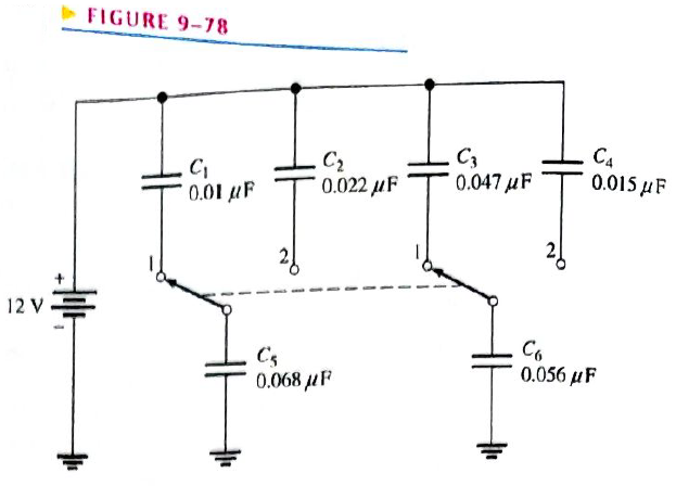
Chapter 9, Problem 48P
How much does the voltage across
Expert Solution & Answer
Want to see the full answer?
Check out a sample textbook solution
Students have asked these similar questions
23. Design a binary counter with the sequence shown in the state diagram of Figure 9–75.
Up
(1
Down
FIGURE 9-75
THE SWITCH HAS BetN
W PositIOn 1 FoR
A LONG TiME
THE INITAL VOLTnsE
ACposs THE Lf
CAPACITUR IS ZERO,
25V
Fwo THE CURRENT i,
AFTER THE SwitCH
Is OPERATZA br E-0
0.5af T
4. For the ripple counter in Figure 9-66, show the complete timing diagram for sixteen clock
pulses. Show the clock, Qo. Qi, and Q2 waveforms.
LLL
Do
DI
D2
CLK
C
C
FIGURE 9-66
Chapter 9 Solutions
Electronics Fundamentals: Circuits, Devices & Applications
Ch. 9 - The area of the plates of a capacitor is...Ch. 9 - A capacitance of 1200pF is the same as 1.2F.Ch. 9 - When two capacitors are in series with a voltage...Ch. 9 - When two capacitors are in parallel with a voltage...Ch. 9 - Prob. 5TFQCh. 9 - Prob. 6TFQCh. 9 - Prob. 7TFQCh. 9 - Prob. 8TFQCh. 9 - Voltage leads current in a capacitor.Ch. 9 - Prob. 10TFQ
Ch. 9 - Prob. 1STCh. 9 - Prob. 2STCh. 9 - Prob. 3STCh. 9 - A capacitance of 1000pF is smaller than 0.01F...Ch. 9 - Prob. 5STCh. 9 - Prob. 6STCh. 9 - Prob. 7STCh. 9 - Prob. 8STCh. 9 - Prob. 9STCh. 9 - Prob. 10STCh. 9 - Prob. 11STCh. 9 - Prob. 12STCh. 9 - Prob. 13STCh. 9 - A sinusoidal voltage is applied across a...Ch. 9 - Prob. 15STCh. 9 - Prob. 1TSCCh. 9 - Prob. 2TSCCh. 9 - Prob. 3TSCCh. 9 - Prob. 4TSCCh. 9 - Determine the cause for each set of symptoms....Ch. 9 - Find the capacitance when Q=50CandV=10V. Find the...Ch. 9 - Convert the following values from microfarads to...Ch. 9 - Convert the following values from picofarads to...Ch. 9 - Convert the following values from farads to...Ch. 9 - What size capacitor is capable of storing 10mJ of...Ch. 9 - A mica capacitor has a plate area of 20cm2 and a...Ch. 9 - An air capacitor has plates with an area of 0.1m2....Ch. 9 - A student wants to construct a 1F capacity out of...Ch. 9 - A student decide to construct a capacitor using...Ch. 9 - At ambient temperature (25oC), a certain capacitor...Ch. 9 - A 0.001F capacitor has a positive temperature...Ch. 9 - In the construction of a stacked-foil mica...Ch. 9 - What type of capacitor has the higher dielectric...Ch. 9 - Show how to connect an electrolytic capacitor...Ch. 9 - Determine the value of the typographically labeled...Ch. 9 - Name two types of electrolytic capacitors. How do...Ch. 9 - Prob. 17PCh. 9 - Five 1000pF capacitors are in series. What is the...Ch. 9 - Find the total capacitance for each circuit in...Ch. 9 - For each circuit in Figure 9-65 determine the...Ch. 9 - The total charge stored by the series capacitors...Ch. 9 - Determine CT for each circuit in Figure 9-67.Ch. 9 - Determine the total capacitance and total charge...Ch. 9 - Assume you need a total capacitance of 2.1F in a...Ch. 9 - Determine the time constant for each of the...Ch. 9 - Determine how long it takes the capacitor to reach...Ch. 9 - In the circuit of Figure 9-69, the capacitor...Ch. 9 - In Figure 9-70, the capacitor is charged to 25 V....Ch. 9 - Repeat Problem 27 for the following time...Ch. 9 - Repeat Problem 28 for the following time...Ch. 9 - Deterimine XC for a 0.0047F capacitor at each of...Ch. 9 - What is the value of the total capacitive...Ch. 9 - For the circuit in Figure 9-72, find the reactance...Ch. 9 - Prob. 34PCh. 9 - A sinusoidal voltage of 20Vrms produces an rms...Ch. 9 - A 10 kHz voltage is applied to a 0.0047F...Ch. 9 - Determine the true power and the reactive power in...Ch. 9 - If another capacitor is connected in parallel with...Ch. 9 - Ideally, what should the reactance of a bypass...Ch. 9 - Two series capacitors (one 1F, the other of...Ch. 9 - Prob. 41PCh. 9 - How long does it take C to charge to 8 V in Figure...Ch. 9 - Detemine the time constant for the circuit in...Ch. 9 - In Figure 9-74, the capacitor initially is...Ch. 9 - The capacitor in Figure 9-75 is uncharged when the...Ch. 9 - Determine the ac voltage across each capacitor and...Ch. 9 - Find the value of C1 in Figure 9-77.Ch. 9 - How much does the voltage across C5andC6 change...Ch. 9 - If C4 in Figure 9-76 is open determine the voltage...Ch. 9 - Prob. 50PCh. 9 - Prob. 51PCh. 9 - Prob. 52PCh. 9 - Prob. 53PCh. 9 - Prob. 54P
Knowledge Booster


Learn more about
Need a deep-dive on the concept behind this application? Look no further. Learn more about this topic, electrical-engineering and related others by exploring similar questions and additional content below.Similar questions
- 5. The hypotenuse has a length of 65 in., and side A has a length of 31 in. What is angle X?arrow_forwardVery urgent. Draw the waveforms of the voltage at the load (RL) end, the voltage at the R end, the voltage at the L end and the current 1 when the switch K is turned to position 2 after a long enough time.arrow_forwardPlz complete =3 upvotesarrow_forward
- 4. The meter movement in Question 3 is to be used as a multirange ammeter. An Ayrton shunt is to be used to provide full-scale current ranges of 5 A, 1 A, and 0.5 A (Figure 9-66). Find the values of . FIGURE 9-66 Ayrton shunt.arrow_forward2. The meter movement described in Question 1 is to be used to construct a multirange voltmeter. The meter is to have voltage ranges of 15 V. 60 V, 150 V, and 300 V (Figure 9-65). Find the values of .arrow_forward4. For the ripple counter in Figure 9-66, show the complete timing diagram for sixteen clock pulses. Show the clock, Qo, Q₁, and Q₂ waveforms. CLK D₁ с +++ Do C D₁₂ Carrow_forward
- Please right proper mostly i am getting copied answer if now I got this copied i will give downvotesarrow_forwardresistor 5. The equivalent constant-current source for the constant-voltage source of Figure 9-59 is (a) a 1.8-A current source in series with a 0.15-2 resistor (b) an 80-A current source in parallel with a 0.15-2 resistor (c) an 80-A current source in parallel with a 100-2 resistor (d) a 1.8-A current source in parallel with a 100-2 resistor 0.15 Q Ty U 001arrow_forward4. For the ripple counter in Figure 9-66, show the complete timing diagram for sixteen clock pulses. Show the clock, Qo, Q1, and Q2 waveforms. CLK FIGURE 9-66 D₁ C lo lo D₁ Q₁ D₂ e₂arrow_forward
- 8. Calculate the de voltages from each terminal to ground for the FETs in Figure 9–58. +15 V -10 V +12 V 8 mA| 6 mA| Rp 1.0 kN Rp 1.5 kN Rp 1.0 kN 3 mA R 10 kM Rs RG 10 ΜΩ RG 10 ΜΩ * 330 N R2 4.7 kN (a) (b)arrow_forward9. Identify each characteristic curve in Figure 9–59 by the type of FET that it represents. -VGS +VGS -VGs -VGS (c) (b) (а)arrow_forwardcan i get a step by step plz and thank youarrow_forward
arrow_back_ios
SEE MORE QUESTIONS
arrow_forward_ios
Recommended textbooks for you
 Delmar's Standard Textbook Of ElectricityElectrical EngineeringISBN:9781337900348Author:Stephen L. HermanPublisher:Cengage Learning
Delmar's Standard Textbook Of Electricity
Electrical Engineering
ISBN:9781337900348
Author:Stephen L. Herman
Publisher:Cengage Learning
8.02x - Lect 21 - Magnetic Materials, Dia- Para- & Ferromagnetism; Author: Lectures by Walter Lewin. They will make you ♥ Physics.;https://www.youtube.com/watch?v=1xFRtdN5IJA;License: Standard Youtube License