
Electronics Fundamentals: Circuits, Devices & Applications
8th Edition
ISBN: 9780135072950
Author: Thomas L. Floyd, David Buchla
Publisher: Prentice Hall
expand_more
expand_more
format_list_bulleted
Concept explainers
Videos
Textbook Question
Chapter 9, Problem 22P
Determine
Expert Solution & Answer
Want to see the full answer?
Check out a sample textbook solution
Students have asked these similar questions
resistor
5.
The equivalent constant-current source for the constant-voltage
source of Figure 9-59 is
(a) a 1.8-A current source in series with a 0.15-2 resistor
(b) an 80-A current source in parallel with a 0.15-2 resistor
(c) an 80-A current source in parallel with a 100-2 resistor
(d) a 1.8-A current source in parallel with a 100-2 resistor
0.15 Q
Ty
U 001
For the amplifier in Figure 9–64. ID(on) = 18 mA at VGS = 10 V,VGS(th) = 2.5 V, and gm = 3000 mS.
Determine VGS
Determine ID
Determine I in the figure
Chapter 9 Solutions
Electronics Fundamentals: Circuits, Devices & Applications
Ch. 9 - The area of the plates of a capacitor is...Ch. 9 - A capacitance of 1200pF is the same as 1.2F.Ch. 9 - When two capacitors are in series with a voltage...Ch. 9 - When two capacitors are in parallel with a voltage...Ch. 9 - Prob. 5TFQCh. 9 - Prob. 6TFQCh. 9 - Prob. 7TFQCh. 9 - Prob. 8TFQCh. 9 - Voltage leads current in a capacitor.Ch. 9 - Prob. 10TFQ
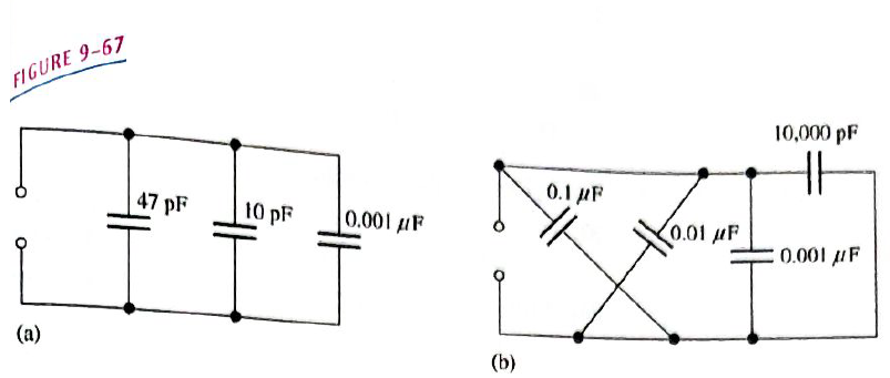
Ch. 9 - Prob. 1STCh. 9 - Prob. 2STCh. 9 - Prob. 3STCh. 9 - A capacitance of 1000pF is smaller than 0.01F...Ch. 9 - Prob. 5STCh. 9 - Prob. 6STCh. 9 - Prob. 7STCh. 9 - Prob. 8STCh. 9 - Prob. 9STCh. 9 - Prob. 10STCh. 9 - Prob. 11STCh. 9 - Prob. 12STCh. 9 - Prob. 13STCh. 9 - A sinusoidal voltage is applied across a...Ch. 9 - Prob. 15STCh. 9 - Prob. 1TSCCh. 9 - Prob. 2TSCCh. 9 - Prob. 3TSCCh. 9 - Prob. 4TSCCh. 9 - Determine the cause for each set of symptoms....Ch. 9 - Find the capacitance when Q=50CandV=10V. Find the...Ch. 9 - Convert the following values from microfarads to...Ch. 9 - Convert the following values from picofarads to...Ch. 9 - Convert the following values from farads to...Ch. 9 - What size capacitor is capable of storing 10mJ of...Ch. 9 - A mica capacitor has a plate area of 20cm2 and a...Ch. 9 - An air capacitor has plates with an area of 0.1m2....Ch. 9 - A student wants to construct a 1F capacity out of...Ch. 9 - A student decide to construct a capacitor using...Ch. 9 - At ambient temperature (25oC), a certain capacitor...Ch. 9 - A 0.001F capacitor has a positive temperature...Ch. 9 - In the construction of a stacked-foil mica...Ch. 9 - What type of capacitor has the higher dielectric...Ch. 9 - Show how to connect an electrolytic capacitor...Ch. 9 - Determine the value of the typographically labeled...Ch. 9 - Name two types of electrolytic capacitors. How do...Ch. 9 - Prob. 17PCh. 9 - Five 1000pF capacitors are in series. What is the...Ch. 9 - Find the total capacitance for each circuit in...Ch. 9 - For each circuit in Figure 9-65 determine the...Ch. 9 - The total charge stored by the series capacitors...Ch. 9 - Determine CT for each circuit in Figure 9-67.Ch. 9 - Determine the total capacitance and total charge...Ch. 9 - Assume you need a total capacitance of 2.1F in a...Ch. 9 - Determine the time constant for each of the...Ch. 9 - Determine how long it takes the capacitor to reach...Ch. 9 - In the circuit of Figure 9-69, the capacitor...Ch. 9 - In Figure 9-70, the capacitor is charged to 25 V....Ch. 9 - Repeat Problem 27 for the following time...Ch. 9 - Repeat Problem 28 for the following time...Ch. 9 - Deterimine XC for a 0.0047F capacitor at each of...Ch. 9 - What is the value of the total capacitive...Ch. 9 - For the circuit in Figure 9-72, find the reactance...Ch. 9 - Prob. 34PCh. 9 - A sinusoidal voltage of 20Vrms produces an rms...Ch. 9 - A 10 kHz voltage is applied to a 0.0047F...Ch. 9 - Determine the true power and the reactive power in...Ch. 9 - If another capacitor is connected in parallel with...Ch. 9 - Ideally, what should the reactance of a bypass...Ch. 9 - Two series capacitors (one 1F, the other of...Ch. 9 - Prob. 41PCh. 9 - How long does it take C to charge to 8 V in Figure...Ch. 9 - Detemine the time constant for the circuit in...Ch. 9 - In Figure 9-74, the capacitor initially is...Ch. 9 - The capacitor in Figure 9-75 is uncharged when the...Ch. 9 - Determine the ac voltage across each capacitor and...Ch. 9 - Find the value of C1 in Figure 9-77.Ch. 9 - How much does the voltage across C5andC6 change...Ch. 9 - If C4 in Figure 9-76 is open determine the voltage...Ch. 9 - Prob. 50PCh. 9 - Prob. 51PCh. 9 - Prob. 52PCh. 9 - Prob. 53PCh. 9 - Prob. 54P
Knowledge Booster


Learn more about
Need a deep-dive on the concept behind this application? Look no further. Learn more about this topic, electrical-engineering and related others by exploring similar questions and additional content below.Similar questions
- Determine VDS for the amplifier in Figure 9-64. ID(on) = 18 mA at VGS = 10 %3D V,VGS(th) = 2.5 V, and gm = 3000 mS. VDD +20 V Rp 1.0 kN C2 Vout R1 18 kN 10 μF Vin o RL 10 kN 10 μF R2 6.8 kNarrow_forwardTHE SWITCH HAS BetN W PositIOn 1 FoR A LONG TiME THE INITAL VOLTnsE ACposs THE Lf CAPACITUR IS ZERO, 25V Fwo THE CURRENT i, AFTER THE SwitCH Is OPERATZA br E-0 0.5af Tarrow_forwardA capacitor and resistor are connected in series. The resistor has a resistance of 26 ohms and the capacitor has a capacitive resistance of 16 ohms. What is the impedance of the circuit?arrow_forward
- Very urgent. Draw the waveforms of the voltage at the load (RL) end, the voltage at the R end, the voltage at the L end and the current 1 when the switch K is turned to position 2 after a long enough time.arrow_forwardPlz complete itarrow_forwarda capacitor and resistor are connected in series. the resistor has a resistance of 26 ohms and the capacitor has a capacitive reactance of 16 ohms. what is the impedance of the circuit?arrow_forward
- What should be Rl and what is Pmax in order to transfer maximum power from the source to the load.arrow_forwardAn R-L series circuit contains two resistors and two inductors. Th resistors are 68 ohms and 124 ohms. The inductors have inductive reactances of 44 ohms and 225 ohms. the total voltage is 240 volts. find the voltage drop across the 124 ohm resistor.arrow_forwarda resistor and and capacitor are connected in parallel to a 277 v 60 hz power source. the resistor has a value of 50 ohms and the capacitor has a value of 40 uf what is the circuit power factor.arrow_forward
arrow_back_ios
SEE MORE QUESTIONS
arrow_forward_ios
Recommended textbooks for you
 Delmar's Standard Textbook Of ElectricityElectrical EngineeringISBN:9781337900348Author:Stephen L. HermanPublisher:Cengage Learning
Delmar's Standard Textbook Of Electricity
Electrical Engineering
ISBN:9781337900348
Author:Stephen L. Herman
Publisher:Cengage Learning
8.02x - Lect 21 - Magnetic Materials, Dia- Para- & Ferromagnetism; Author: Lectures by Walter Lewin. They will make you ♥ Physics.;https://www.youtube.com/watch?v=1xFRtdN5IJA;License: Standard Youtube License