
Electronics Fundamentals: Circuits, Devices & Applications
8th Edition
ISBN: 9780135072950
Author: Thomas L. Floyd, David Buchla
Publisher: Prentice Hall
expand_more
expand_more
format_list_bulleted
Concept explainers
Videos
Textbook Question
Chapter 9, Problem 14P
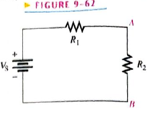
Show how to connect an electrolytic capacitor across points A and B in Figure 9-62.
Expert Solution & Answer
Want to see the full answer?
Check out a sample textbook solution
Students have asked these similar questions
A 22-k resistor and a 0.02-F capacitor are connected in series to a 5-V source. How long will it take the capacitor to charge to 3.4 V
Select one:
a. 0.501 ms
b. 0.66 ms
c. 0.44 ms
d. 0.70 ms
I am having trouble with this problem it might be the dot notation for the inductors but I am not entierly sure that is the only issue I am having
the shunt capacitance is a capacitor
O a. Between a phase and the ground
O b. between phases and a phase to ground
c. none of the answers
O d. Between phases
Chapter 9 Solutions
Electronics Fundamentals: Circuits, Devices & Applications
Ch. 9 - The area of the plates of a capacitor is...Ch. 9 - A capacitance of 1200pF is the same as 1.2F.Ch. 9 - When two capacitors are in series with a voltage...Ch. 9 - When two capacitors are in parallel with a voltage...Ch. 9 - Prob. 5TFQCh. 9 - Prob. 6TFQCh. 9 - Prob. 7TFQCh. 9 - Prob. 8TFQCh. 9 - Voltage leads current in a capacitor.Ch. 9 - Prob. 10TFQ
Ch. 9 - Prob. 1STCh. 9 - Prob. 2STCh. 9 - Prob. 3STCh. 9 - A capacitance of 1000pF is smaller than 0.01F...Ch. 9 - Prob. 5STCh. 9 - Prob. 6STCh. 9 - Prob. 7STCh. 9 - Prob. 8STCh. 9 - Prob. 9STCh. 9 - Prob. 10STCh. 9 - Prob. 11STCh. 9 - Prob. 12STCh. 9 - Prob. 13STCh. 9 - A sinusoidal voltage is applied across a...Ch. 9 - Prob. 15STCh. 9 - Prob. 1TSCCh. 9 - Prob. 2TSCCh. 9 - Prob. 3TSCCh. 9 - Prob. 4TSCCh. 9 - Determine the cause for each set of symptoms....Ch. 9 - Find the capacitance when Q=50CandV=10V. Find the...Ch. 9 - Convert the following values from microfarads to...Ch. 9 - Convert the following values from picofarads to...Ch. 9 - Convert the following values from farads to...Ch. 9 - What size capacitor is capable of storing 10mJ of...Ch. 9 - A mica capacitor has a plate area of 20cm2 and a...Ch. 9 - An air capacitor has plates with an area of 0.1m2....Ch. 9 - A student wants to construct a 1F capacity out of...Ch. 9 - A student decide to construct a capacitor using...Ch. 9 - At ambient temperature (25oC), a certain capacitor...Ch. 9 - A 0.001F capacitor has a positive temperature...Ch. 9 - In the construction of a stacked-foil mica...Ch. 9 - What type of capacitor has the higher dielectric...Ch. 9 - Show how to connect an electrolytic capacitor...Ch. 9 - Determine the value of the typographically labeled...Ch. 9 - Name two types of electrolytic capacitors. How do...Ch. 9 - Prob. 17PCh. 9 - Five 1000pF capacitors are in series. What is the...Ch. 9 - Find the total capacitance for each circuit in...Ch. 9 - For each circuit in Figure 9-65 determine the...Ch. 9 - The total charge stored by the series capacitors...Ch. 9 - Determine CT for each circuit in Figure 9-67.Ch. 9 - Determine the total capacitance and total charge...Ch. 9 - Assume you need a total capacitance of 2.1F in a...Ch. 9 - Determine the time constant for each of the...Ch. 9 - Determine how long it takes the capacitor to reach...Ch. 9 - In the circuit of Figure 9-69, the capacitor...Ch. 9 - In Figure 9-70, the capacitor is charged to 25 V....Ch. 9 - Repeat Problem 27 for the following time...Ch. 9 - Repeat Problem 28 for the following time...Ch. 9 - Deterimine XC for a 0.0047F capacitor at each of...Ch. 9 - What is the value of the total capacitive...Ch. 9 - For the circuit in Figure 9-72, find the reactance...Ch. 9 - Prob. 34PCh. 9 - A sinusoidal voltage of 20Vrms produces an rms...Ch. 9 - A 10 kHz voltage is applied to a 0.0047F...Ch. 9 - Determine the true power and the reactive power in...Ch. 9 - If another capacitor is connected in parallel with...Ch. 9 - Ideally, what should the reactance of a bypass...Ch. 9 - Two series capacitors (one 1F, the other of...Ch. 9 - Prob. 41PCh. 9 - How long does it take C to charge to 8 V in Figure...Ch. 9 - Detemine the time constant for the circuit in...Ch. 9 - In Figure 9-74, the capacitor initially is...Ch. 9 - The capacitor in Figure 9-75 is uncharged when the...Ch. 9 - Determine the ac voltage across each capacitor and...Ch. 9 - Find the value of C1 in Figure 9-77.Ch. 9 - How much does the voltage across C5andC6 change...Ch. 9 - If C4 in Figure 9-76 is open determine the voltage...Ch. 9 - Prob. 50PCh. 9 - Prob. 51PCh. 9 - Prob. 52PCh. 9 - Prob. 53PCh. 9 - Prob. 54P
Knowledge Booster


Learn more about
Need a deep-dive on the concept behind this application? Look no further. Learn more about this topic, electrical-engineering and related others by exploring similar questions and additional content below.Similar questions
- A 15-F AC capacitor is connected in series with a 50 resistor. The capacitor has a voltage rating of 600 WVDC. The capacitor and resistor are connected to a 480-V, 60-Hz circuit. Is the voltage rating of the capacitor sufficient for this connection?arrow_forwardAn RC series circuit is connected to a 120-V, 60-Hz power source. The resistor is 25 and has a voltage drop of 65 volts. What is the capacitance of the capacitor?arrow_forwardA postage stamp mica capacitor has the following color marks starting at the upper left dot: yellow, violet, brown, green, no color, and blue. What are the capacitance value, tolerance, and voltage rating of this capacitor?arrow_forward
- find total capacitance and total charge. C1 = 20pF C2 = 30pF 5V C3 = 30pF C5 10pF C4 30pFarrow_forwardA 470- uF capacitor is connected in series with a 120-k2 resistor. How long will it take the capacitor to charge completely?arrow_forwardThe capacitor dissipation factor is the ratio of inductive reactance to its resistance resistance to its inductive reactance resistance to its capacitive reactance capacitive reactance to its resistancearrow_forward
- 3. A resistor and a capacitor are connected in parallel across a 120 V DC source. Determine the voltages across the resistor and the capacitor.arrow_forwardProblem: 25 mH m Find Leq In below figure. 10 mH m 60 mH m 20 mH m 30 mH m -o b L 0000arrow_forwardBy convention, the sign of reactive power to an inductance is and the sign of reactive power to a capacitance isarrow_forward
- 1. A purely resistive circuit the current is leading by 90° with respect to voltage. 2. A purely inductive circuit the current is lag behind the voltage by 90°. 3. A purely capacitive circuit the current is lead by 90° with respect to the voltage. 4. A capacitor element stored magnetic energy. 5. An inductor element stored electrical energy. 6. Resistor elements consume power. 7. Angle between current and voltage is called power. 8. The power factor angle for a purely resistive is zero. 9. The power factor angle for a purely inductive load is -90°. 10. The power factor of a purely capacitive is leading.arrow_forwardProblem 9: A combination of series and parallel connections of capacitors is shown in the figure. The sizes of these capacitors are given by the follow data: C1 = 4.7 µF C2 = 3.5 µF C3 = 7.4 µF C4 = 2.8 µF C5 = 0.95 µF C6 = 15.5 µF C4 C2 Find the total capacitance of the combination of capacitors in microfarads.arrow_forwardWhat is the equivalent resistance ?? and what is the total inductance ??arrow_forward
arrow_back_ios
SEE MORE QUESTIONS
arrow_forward_ios
Recommended textbooks for you
 Delmar's Standard Textbook Of ElectricityElectrical EngineeringISBN:9781337900348Author:Stephen L. HermanPublisher:Cengage Learning
Delmar's Standard Textbook Of Electricity
Electrical Engineering
ISBN:9781337900348
Author:Stephen L. Herman
Publisher:Cengage Learning
Capacitors Explained - The basics how capacitors work working principle; Author: The Engineering Mindset;https://www.youtube.com/watch?v=X4EUwTwZ110;License: Standard YouTube License, CC-BY