
Statics and Mechanics of Materials (5th Edition)
5th Edition
ISBN: 9780134382593
Author: Russell C. Hibbeler
Publisher: PEARSON
expand_more
expand_more
format_list_bulleted
Concept explainers
Videos
Textbook Question
Chapter 8.6, Problem 28P
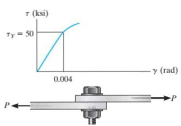
The shear stress-strain diagram for an alloy is shown in the figure. If a bolt having a diameter of 0.25 in. is made of this material and used in the lap joint, determine the modulus of elasticity E and the force P required to cause the material to yield, Take v = 0.3.
Prob. 8-28.
Expert Solution & Answer
Want to see the full answer?
Check out a sample textbook solution
Students have asked these similar questions
8-21. The elastic portion of the stress-strain diagram for
an aluminum alloy is shown in the figure. The specimen
from which it was obtained has an original diameter of
12.7 mm and a gage length of 50.8 mm. When the applied
load on the specimen is 50 kN, the diameter is 12.67494 mm.
Determine Poisson's ratio for the material.
(MPa)
490
(mm/mm)
0.007
8-22. The elastic portion of the stress-strain diagram for an
aluminum alloy is shown in the figure. The specimen from
which it was obtained has an original diameter of 12.7 mm
and a gage length of 50.8 mm. If a load of P - 60 kN is
applied to the specimen, determine its new diameter and
length. Take v-0.35.
a (MPa)
490
(mm/mm)
0.007
8-21. The elastic portion of the stress-strain diagram for
an aluminum alloy is shown in the figure. The specimen
from which it was obtained has an original diameter of
12.7 mm and a gage length of 50.8 mm. When the applied
load on the specimen is 50 kN, the diameter is 12.67494 mm.
Determine Poisson's ratio for the material.
8-22. The elastic portion of the stress-strain diagram for an
aluminum alloy is shown in the figure. The specimen from
which it was obtained has an original diameter of 12.7 mm
and a gage length of 50.8 mm. If a load of P = 60 kN is
applied to the specimen, determine its new diameter and
length. Take v = 0.35.
σ (MPa)
490
0.007
Probs. 8-21/22
€ (mm/mm)
Chapter 8 Solutions
Statics and Mechanics of Materials (5th Edition)
Ch. 8.4 - Define a homogeneous material.Ch. 8.4 - Prob. 2FPCh. 8.4 - Prob. 3FPCh. 8.4 - Prob. 4FPCh. 8.4 - Prob. 5FPCh. 8.4 - As the temperature increases the modulus of...Ch. 8.4 - Prob. 7FPCh. 8.4 - Prob. 8FPCh. 8.4 - Prob. 9FPCh. 8.4 - Prob. 10FP
Ch. 8.4 - The material for the 50-mm-long specimen has the...Ch. 8.4 - If the elongation of wire BC is 0.2 mm after the...Ch. 8.4 - A tension test was performed on a steel specimen...Ch. 8.4 - Data taken from a stressstrain test for a ceramic...Ch. 8.4 - Data taken from a stressstrain test for a ceramic...Ch. 8.4 - Prob. 4PCh. 8.4 - The stress-strain diagram for a steel alloy having...Ch. 8.4 - Prob. 6PCh. 8.4 - The rigid beam is supported by a pin at C and an...Ch. 8.4 - The rigid beam is supported by a pin at C and an...Ch. 8.4 - Prob. 9PCh. 8.4 - The stressstrain diagram for an aluminum alloy...Ch. 8.4 - The stressstrain diagram for an aluminum alloy...Ch. 8.4 - Prob. 12PCh. 8.4 - A bar having a length of 5 in. and cross-sectional...Ch. 8.4 - The rigid pipe is supported by a pin at A and an...Ch. 8.4 - The rigid pipe is supported by a pin at A and an...Ch. 8.4 - Prob. 16PCh. 8.4 - The rigid beam is supported by a pin at C and an...Ch. 8.4 - Prob. 18PCh. 8.4 - Prob. 19PCh. 8.6 - A 100 mm long rod has a diameter of 15 mm. If an...Ch. 8.6 - A solid circular rod that is 600 mm long and 20 mm...Ch. 8.6 - Prob. 15FPCh. 8.6 - Prob. 16FPCh. 8.6 - The acrylic plastic rod is 200 mm long and 15 mm...Ch. 8.6 - The plug has a diameter of 30 mm and fits within a...Ch. 8.6 - The elastic portion of the stress-strain diagram...Ch. 8.6 - The elastic portion of the stress-strain diagram...Ch. 8.6 - The brake pads for a bicycle tire arc made of...Ch. 8.6 - The lap joint is connected together using a 1.25...Ch. 8.6 - The lap joint is connected together using a 1.25...Ch. 8.6 - Prob. 27PCh. 8.6 - The shear stress-strain diagram for an alloy is...Ch. 8.6 - Prob. 29PCh. 8 - The elastic portion of the tension stress-strain...Ch. 8 - Prob. 2RPCh. 8 - Prob. 3RPCh. 8 - Prob. 4RPCh. 8 - Prob. 5RPCh. 8 - Prob. 6RPCh. 8 - The stress-strain diagram for polyethylene, which...Ch. 8 - The pipe with two rigid caps attached to its ends...Ch. 8 - Prob. 9RPCh. 8 - Prob. 10RP
Knowledge Booster


Learn more about
Need a deep-dive on the concept behind this application? Look no further. Learn more about this topic, mechanical-engineering and related others by exploring similar questions and additional content below.Similar questions
- 3–26. The thin-walled tube is subjected to an axial force of 40 kN. If the tube elongates 3 mm and its circumference decreases 0.09 mm, determine the modulus of elasticity, Poisson's ratio, and the shear modulus of the tube's material. The material behaves elastically. 40 kN 900 mm | 10 mm 40 kN 12.5 mmarrow_forwardThe shear stress–strain diagram for an alloy is shown in the figure. If a bolt having a diameter of 0.25 in. is made of this material and used in the lap joint, determine the modulus of elasticity E and the force P required to cause the material to yield. Take n = 0.3.arrow_forward8-19. The two bars are made of polystyrene, which has the stress-strain diagram shown. Determine the cross-sectional area of each bar so that the bars rupture simultaneously when the load P- 13.5 kN. Assume that buckling does not occur. -1.2 m- a(MPa) 175 140 105 compression 70 35 Hptension (mm/um) 0.20 0.40 0.60 0.80arrow_forward
- 8-10. A bar having a length of 125 mm and cross-sectional area of 4375 mm² is subjected to an axial force of 40 kN. If the bar stretches 0.05 mm, determine the modulus of elasticity of the material. The material has linear-elastic behavior. 40 kN -125 mm 40 kNarrow_forwardProblem 7 The shear stress-strain diagram for an alloy is shown in the figure. If a bolt having a diameter of 0.25 in. is made of this material and used in the lap joint, determine the modulus of elasticity E and the force P required to cause the material to yield. Take v=0.3. 7 (ksi) Ty= 50 0.004 y (rad)arrow_forwardThe strain at a point is 780x10-6 in the x, 400x10-5 in the y and -500x10-6 in the z direction. Determine the stress state if the Young's modulus is 10,640 ksi and v = 0.33.arrow_forward
- *3-28. The elastic portion of the stress-strain diagram for a steel alloy is shown in the figure. The specimen from which it was obtained had an original diameter of 13 mm and a gauge length of 50 mm. If a load of P- 20 kN is applied to the specimen, determine its diameter and gauge length. Take v - 0.4. o(MPa) 400 e(mm/mm) 0.002arrow_forwardA bar having a length of 125 mm and cross-sectional area of 437.5 mm2 is subjected to an axial force of 40 kN. If 3-13. the bar stretches 0.05 mm, determine the modulus of elasticity of the material. The material has linear-elastic behavior. 40 kN 40 kN -125 mm Prob. 3–13arrow_forwardA copper bar with a square cross section is inserted into a square rigid tube as shown in the figure. The length of the copper bar is 1.2 m and the area of the cross section is 300 mm2. The bar is subjected to a force P that applies a uniformly distributed pressure to the copper. Calculate the force P if the longitudinal displacement of the bar is 2 mm. Assume that the modulus of elasticity of the bar is E = 110 GPa and Poisson’s ratio is v = 0.33. Disregard friction between the copper and the rigid tube.arrow_forward
- The elastic portion of the stress- strain diagram for the 2014-T6 aluminum is shown in the figure. A short cylindrical block, made of this material and has a diameter of 22 mm, is placed in the smooth jaws of a vise, and squeezed until the axial load applied is P= 45 kN. If the material has a Poisson's ratio of = 0.35, determine the new diameter (mm) of the cylindrical block.arrow_forward8-18. The two bars are made of polystyrene, which has the stress-strain diagram shown. If the cross-sectional area of bar AB is 975 mm² and BC is 2600 mm?, determine the largest force P that can be supported before any member ruptures. Assume that buckling does not occur. 1m (MPa) 175 140 105 compression 70 35 H plension e (mm/mm) 0.20 0.40 0.60 0.80arrow_forward5. The rigid bar is supported by a smooth pin and two rods as shown. Neglect the weight of the rigid bar. The assembly is initially stress-free. Determine the stress in each rod if the temperature increases by 25°C after a load W = 100 kN is applied. The steel rod has an area of 320 mm² with a = 11.7 µm/ (m°C) and E = 200 GPa. For the bronze rod, it has an area of 1380 mm² with a = 18.9 μm/ ( mºC) and E = 83 GPa. Bronze 3 m Steel 1.5 m 1.0 m - O k 2.5 m 1.5 m W 6. Three wires are used to support the 150-lb force. The wires AB and AC are made of steel, and wire AD is made of copper. Assume that the three wires have constant cross-sectional area A = 0.0123 in². For steel wire, a = 8 x 10⁶ in/ (inºF) and E = 29000 ksi and for copper wire, a = 9.6 x 10⁻⁶ in/ (inºF) and E = 17000 ksi. Calculate the axial force exerted by the three wires if the temperature is raised by 80°F. Answer: Pst = 10 lb, Pcu = 136 lb B D 40 in. 60 in. 45°-45° 60 in. A 150 lbarrow_forward
arrow_back_ios
SEE MORE QUESTIONS
arrow_forward_ios
Recommended textbooks for you
 Mechanics of Materials (MindTap Course List)Mechanical EngineeringISBN:9781337093347Author:Barry J. Goodno, James M. GerePublisher:Cengage Learning
Mechanics of Materials (MindTap Course List)
Mechanical Engineering
ISBN:9781337093347
Author:Barry J. Goodno, James M. Gere
Publisher:Cengage Learning
EVERYTHING on Axial Loading Normal Stress in 10 MINUTES - Mechanics of Materials; Author: Less Boring Lectures;https://www.youtube.com/watch?v=jQ-fNqZWrNg;License: Standard YouTube License, CC-BY