
Statics and Mechanics of Materials (5th Edition)
5th Edition
ISBN: 9780134382593
Author: Russell C. Hibbeler
Publisher: PEARSON
expand_more
expand_more
format_list_bulleted
Concept explainers
Videos
Textbook Question
Chapter 8, Problem 7RP
The stress-strain diagram for polyethylene, which is used to sheath coaxial cables, is determined from testing a specimen that has a gage length of 10 in. If a load P on the specimen develops a strain of ϵ = 0.024 in,/in., determine the approximate length of the specimen, measured between the gage points, when the load is removed. Assume the specimen recovers elastically.
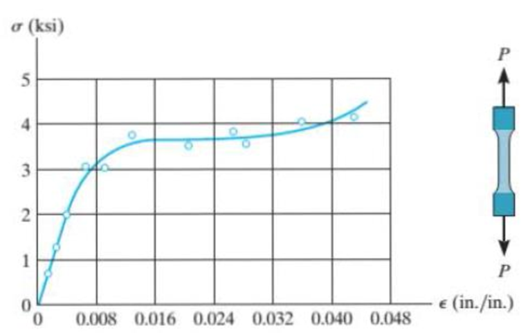
Prob. R8-7
Expert Solution & Answer
Want to see the full answer?
Check out a sample textbook solution
Students have asked these similar questions
A thin polymer plate PQR is deformed such
that corner Q is displaced downward a
distance L = 0.10 in. to new position Q' as
shown. Determine the magnitude of the
shear strain at Q' associated with the two
edges (PQ and QR).
P
25 in.
7982 μrad
6862 μrad
09533 μrad
O6186 prad
O8600 μrad
4 in.
R
10 in.
L
X
A thin polymer plate PQR is deformed such that corner Q is displaced downward a distance L = 0.10 in. to new position Q' as shown.
Determine the magnitude of the shear strain at Q' associated with the two edges (PQ and QR).
P
25 in.
6862 μrad
8014 μrad
O 7358 μrad
O 4241 urad
O 8668 μrad
4 in.
R
10 in.
X
The two bars are used to support load P. When unloaded, joint B has coordinates (0, 0). After load P is applied, joint B moves to the
coordinate position (-0.47 in., -0.16 in.). Assume a - 17 ft, b-34 ft, c-12 ft, and d - 24 ft. Determine the normal strain in each bar.
Answer:
EAB-
T
EBC
i
P
a
e
(1)
B
UE
με
b
(2)
C
d
Chapter 8 Solutions
Statics and Mechanics of Materials (5th Edition)
Ch. 8.4 - Define a homogeneous material.Ch. 8.4 - Prob. 2FPCh. 8.4 - Prob. 3FPCh. 8.4 - Prob. 4FPCh. 8.4 - Prob. 5FPCh. 8.4 - As the temperature increases the modulus of...Ch. 8.4 - Prob. 7FPCh. 8.4 - Prob. 8FPCh. 8.4 - Prob. 9FPCh. 8.4 - Prob. 10FP
Ch. 8.4 - The material for the 50-mm-long specimen has the...Ch. 8.4 - If the elongation of wire BC is 0.2 mm after the...Ch. 8.4 - A tension test was performed on a steel specimen...Ch. 8.4 - Data taken from a stressstrain test for a ceramic...Ch. 8.4 - Data taken from a stressstrain test for a ceramic...Ch. 8.4 - Prob. 4PCh. 8.4 - The stress-strain diagram for a steel alloy having...Ch. 8.4 - Prob. 6PCh. 8.4 - The rigid beam is supported by a pin at C and an...Ch. 8.4 - The rigid beam is supported by a pin at C and an...Ch. 8.4 - Prob. 9PCh. 8.4 - The stressstrain diagram for an aluminum alloy...Ch. 8.4 - The stressstrain diagram for an aluminum alloy...Ch. 8.4 - Prob. 12PCh. 8.4 - A bar having a length of 5 in. and cross-sectional...Ch. 8.4 - The rigid pipe is supported by a pin at A and an...Ch. 8.4 - The rigid pipe is supported by a pin at A and an...Ch. 8.4 - Prob. 16PCh. 8.4 - The rigid beam is supported by a pin at C and an...Ch. 8.4 - Prob. 18PCh. 8.4 - Prob. 19PCh. 8.6 - A 100 mm long rod has a diameter of 15 mm. If an...Ch. 8.6 - A solid circular rod that is 600 mm long and 20 mm...Ch. 8.6 - Prob. 15FPCh. 8.6 - Prob. 16FPCh. 8.6 - The acrylic plastic rod is 200 mm long and 15 mm...Ch. 8.6 - The plug has a diameter of 30 mm and fits within a...Ch. 8.6 - The elastic portion of the stress-strain diagram...Ch. 8.6 - The elastic portion of the stress-strain diagram...Ch. 8.6 - The brake pads for a bicycle tire arc made of...Ch. 8.6 - The lap joint is connected together using a 1.25...Ch. 8.6 - The lap joint is connected together using a 1.25...Ch. 8.6 - Prob. 27PCh. 8.6 - The shear stress-strain diagram for an alloy is...Ch. 8.6 - Prob. 29PCh. 8 - The elastic portion of the tension stress-strain...Ch. 8 - Prob. 2RPCh. 8 - Prob. 3RPCh. 8 - Prob. 4RPCh. 8 - Prob. 5RPCh. 8 - Prob. 6RPCh. 8 - The stress-strain diagram for polyethylene, which...Ch. 8 - The pipe with two rigid caps attached to its ends...Ch. 8 - Prob. 9RPCh. 8 - Prob. 10RP
Knowledge Booster


Learn more about
Need a deep-dive on the concept behind this application? Look no further. Learn more about this topic, mechanical-engineering and related others by exploring similar questions and additional content below.Similar questions
- The rigid bar ABC pivots about support B. After application of load P, end C of the rigid bar moves upward by 0.07 in. If the length of bar (1) is L₁-41 in, determine the average normal strain in bar (1). Assume that a-135 in, b-39 in, and c-0.15 in a b C Rigid bar 4 Part 1 * Incorrect Determine the distance that end A of the rigid bar moves downward, if end C moves upward by 0.07 in Answer: in VA i 00361arrow_forwardThe 60° strain rosette is mounted on the surface of the bracket. The following readings are obtained for each gage: Pa = -780(10-6), Pb = 400(10-6), and Pc = 500(10-6). Determine (a) the principal strains and (b) the maximumin-plane shear strain and associated average normal strain. In each case show the deformed element due to these strains.arrow_forwardThe strain components ɛx = 466 µE, ɛy = -524 µe, and yxy = -646 µrad are given for a point in a body subjected to plane strain. Determine the angle Op corresponding to the orientation of the principal planes at the point. -12.12° None of the above -17.93° -13.75° -10.36° -16.56°arrow_forward
- 2. If the load P on the beam causes the end C to be displaced 10 mm downward, determine the normal strain in wires CE and BD. 4 m [Ans: ECE = 0.0025; ɛBD = 0.00107]arrow_forward8-11. A specimen is originally 300 mm long, has a diameter of 12 mm, and is subjected to a force of 2.5 kN. When the force is increased from 2.5 kN to 9 kN, the specimen elongates 0.225 mm. Determine the modulus of elasticity for the material if it remains linear elastic. a (MPa) 31.50 26.25 21.00 15.75 10.50 625 N 5.25 « (mm/mm) 0.05 010arrow_forwardThe strain at a point is 780x10-6 in the x, 400x10-5 in the y and -500x10-6 in the z direction. Determine the stress state if the Young's modulus is 10,640 ksi and v = 0.33.arrow_forward
- 8-21. The elastic portion of the stress-strain diagram for an aluminum alloy is shown in the figure. The specimen from which it was obtained has an original diameter of 12.7 mm and a gage length of 50.8 mm. When the applied load on the specimen is 50 kN, the diameter is 12.67494 mm. Determine Poisson's ratio for the material. 8-22. The elastic portion of the stress-strain diagram for an aluminum alloy is shown in the figure. The specimen from which it was obtained has an original diameter of 12.7 mm and a gage length of 50.8 mm. If a load of P = 60 kN is applied to the specimen, determine its new diameter and length. Take v = 0.35. σ (MPa) 490 0.007 Probs. 8-21/22 € (mm/mm)arrow_forwardThe normal strain in a suspended bar of material of varying cross section due to its own weight is given by the expression γy/3E where γ = 2.9 lb/in.3 is the specific weight of the material, y = 3.4 in. is the distance from the free (i.e., bottom) end of the bar, L = 17 in. is the length of the bar, and E = 24000 ksi is a material constant. Determine, (a) the change in length of the bar due to its own weight. (b) the average normal strain over the length L of the bar. (c) the maximum normal strain in the bar.arrow_forwardA pipe is subjected to a tension force of P = 70 kN. The pipe outside diameter is 32 mm, the wall thickness is 6.0 mm, and the elastic modulus is E = 180 GPa. Determine the normal strain in the pipe. P Select one: O a. 0.001263 mm/mm O b. 0.000535 mm/mm O c. 0.000568 mm/mm O d. 0.000794 mm/mm e. 0.001382 mm/mm O f. Nonearrow_forward
- The material for the 50-mm-long specimen has the stress-strain diagram shown. If P = 100 kN, determine the elongation of the specimen.arrow_forwardA strain gauges system mounted at a point on a structural member that is subjected to multiaxial stress, where we have the following readings: E = 1.575 x10-, ɛy = -1.350 x10⁻³ ; ɛz = 2.750 x10⁴;Yxy = 1.300 x10⁻³; Determine the stress components if the member is made of an isotropic material with linear elastic behavior having the following elastic properties: Young's modulus E = 200 Gpa and shear modulus G = 76.9 Gpa; %3D %3D Select onearrow_forwardThe strain rosette shown below was used to obtain normal strain data at a point on the free surface of a 2024-T4 aluminum alloy machine part. The gage readings were Ea = +630μ, b = +450μ, and Ec = +1200μ. Determine (a) The strain components Ex, Ey, and Yay at the point. (b) The stress components o, y, and Tay at the point. Express the stresses in SI units. (c) The principal stresses and the maximum shearing stress at the point. Gage c Y 90° Gage b Gage a 45° -Xarrow_forward
arrow_back_ios
SEE MORE QUESTIONS
arrow_forward_ios
Recommended textbooks for you
 Elements Of ElectromagneticsMechanical EngineeringISBN:9780190698614Author:Sadiku, Matthew N. O.Publisher:Oxford University Press
 Mechanics of Materials (10th Edition)Mechanical EngineeringISBN:9780134319650Author:Russell C. HibbelerPublisher:PEARSON
 Thermodynamics: An Engineering ApproachMechanical EngineeringISBN:9781259822674Author:Yunus A. Cengel Dr., Michael A. BolesPublisher:McGraw-Hill Education
 Control Systems EngineeringMechanical EngineeringISBN:9781118170519Author:Norman S. NisePublisher:WILEY
 Mechanics of Materials (MindTap Course List)Mechanical EngineeringISBN:9781337093347Author:Barry J. Goodno, James M. GerePublisher:Cengage Learning
 Engineering Mechanics: StaticsMechanical EngineeringISBN:9781118807330Author:James L. Meriam, L. G. Kraige, J. N. BoltonPublisher:WILEY
Elements Of Electromagnetics
Mechanical Engineering
ISBN:9780190698614
Author:Sadiku, Matthew N. O.
Publisher:Oxford University Press
Mechanics of Materials (10th Edition)
Mechanical Engineering
ISBN:9780134319650
Author:Russell C. Hibbeler
Publisher:PEARSON
Thermodynamics: An Engineering Approach
Mechanical Engineering
ISBN:9781259822674
Author:Yunus A. Cengel Dr., Michael A. Boles
Publisher:McGraw-Hill Education
Control Systems Engineering
Mechanical Engineering
ISBN:9781118170519
Author:Norman S. Nise
Publisher:WILEY
Mechanics of Materials (MindTap Course List)
Mechanical Engineering
ISBN:9781337093347
Author:Barry J. Goodno, James M. Gere
Publisher:Cengage Learning
Engineering Mechanics: Statics
Mechanical Engineering
ISBN:9781118807330
Author:James L. Meriam, L. G. Kraige, J. N. Bolton
Publisher:WILEY
EVERYTHING on Axial Loading Normal Stress in 10 MINUTES - Mechanics of Materials; Author: Less Boring Lectures;https://www.youtube.com/watch?v=jQ-fNqZWrNg;License: Standard YouTube License, CC-BY