
Statics and Mechanics of Materials (5th Edition)
5th Edition
ISBN: 9780134382593
Author: Russell C. Hibbeler
Publisher: PEARSON
expand_more
expand_more
format_list_bulleted
Videos
Textbook Question
Chapter 8.4, Problem 17P
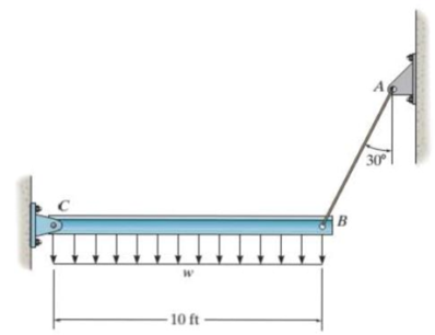
The rigid beam is supported by a pin at C and an A992 steel guy wire AB of length 6 ft. If the wire has a diameter of 0.2 in., determine how much it stretches when a distributed load of w = 200 lb/ft acts on the beam. The wire remains elastic.
Prob. 8–17
Expert Solution & Answer
Want to see the full answer?
Check out a sample textbook solution
Students have asked these similar questions
The simply supported
beam is built up from
three boards by nailing
them together as
A,
В
shown. Determine the
L1
L2
maximum allowable
bf
spacing s of the nails to
support that load, if
each nail can resist a
tf
tw
shear force of V kN.
hw
tf
P=17KN
V=2kN
L1=3.1m
L2=2.5m
bf=120mm
tf=20mm
hw=270mm
tw=15mm
The rigid beam is supported by a pin at C and an A-36 steel guy wire AB. If the wire has a diameter of 0.2 in., determine how much it stretches when a distributed load of w = 100 lb>ft acts on the beam. The material remains elastic.
The rigid beam is supported by a pin at C and an A992 steel guy wire AB of length 6 ft. If the wire has a diameter of 0.2 in., determine how much it stretches when a distributed load of w = 200 lb>ft acts on the beam. The wire remains elastic.
Chapter 8 Solutions
Statics and Mechanics of Materials (5th Edition)
Ch. 8.4 - Define a homogeneous material.Ch. 8.4 - Prob. 2FPCh. 8.4 - Prob. 3FPCh. 8.4 - Prob. 4FPCh. 8.4 - Prob. 5FPCh. 8.4 - As the temperature increases the modulus of...Ch. 8.4 - Prob. 7FPCh. 8.4 - Prob. 8FPCh. 8.4 - Prob. 9FPCh. 8.4 - Prob. 10FP
Ch. 8.4 - The material for the 50-mm-long specimen has the...Ch. 8.4 - If the elongation of wire BC is 0.2 mm after the...Ch. 8.4 - A tension test was performed on a steel specimen...Ch. 8.4 - Data taken from a stressstrain test for a ceramic...Ch. 8.4 - Data taken from a stressstrain test for a ceramic...Ch. 8.4 - Prob. 4PCh. 8.4 - The stress-strain diagram for a steel alloy having...Ch. 8.4 - Prob. 6PCh. 8.4 - The rigid beam is supported by a pin at C and an...Ch. 8.4 - The rigid beam is supported by a pin at C and an...Ch. 8.4 - Prob. 9PCh. 8.4 - The stressstrain diagram for an aluminum alloy...Ch. 8.4 - The stressstrain diagram for an aluminum alloy...Ch. 8.4 - Prob. 12PCh. 8.4 - A bar having a length of 5 in. and cross-sectional...Ch. 8.4 - The rigid pipe is supported by a pin at A and an...Ch. 8.4 - The rigid pipe is supported by a pin at A and an...Ch. 8.4 - Prob. 16PCh. 8.4 - The rigid beam is supported by a pin at C and an...Ch. 8.4 - Prob. 18PCh. 8.4 - Prob. 19PCh. 8.6 - A 100 mm long rod has a diameter of 15 mm. If an...Ch. 8.6 - A solid circular rod that is 600 mm long and 20 mm...Ch. 8.6 - Prob. 15FPCh. 8.6 - Prob. 16FPCh. 8.6 - The acrylic plastic rod is 200 mm long and 15 mm...Ch. 8.6 - The plug has a diameter of 30 mm and fits within a...Ch. 8.6 - The elastic portion of the stress-strain diagram...Ch. 8.6 - The elastic portion of the stress-strain diagram...Ch. 8.6 - The brake pads for a bicycle tire arc made of...Ch. 8.6 - The lap joint is connected together using a 1.25...Ch. 8.6 - The lap joint is connected together using a 1.25...Ch. 8.6 - Prob. 27PCh. 8.6 - The shear stress-strain diagram for an alloy is...Ch. 8.6 - Prob. 29PCh. 8 - The elastic portion of the tension stress-strain...Ch. 8 - Prob. 2RPCh. 8 - Prob. 3RPCh. 8 - Prob. 4RPCh. 8 - Prob. 5RPCh. 8 - Prob. 6RPCh. 8 - The stress-strain diagram for polyethylene, which...Ch. 8 - The pipe with two rigid caps attached to its ends...Ch. 8 - Prob. 9RPCh. 8 - Prob. 10RP
Knowledge Booster


Learn more about
Need a deep-dive on the concept behind this application? Look no further. Learn more about this topic, mechanical-engineering and related others by exploring similar questions and additional content below.Similar questions
- The strut is supported by a pin at C and an A-36 steel (Young’s Modulus is 200 GPa) guy wire AB. If the wire has a diameter of 5 mm, determine how much it stretches when the distributed load acts on the strut. W0=11Kn/marrow_forwardThe horizontal beam is assumed to be rigid while supporting the distributed load. Determine the angle of inclination of the beam after the load is applied. Each support consists of a wooden post with a diameter of 120 mm and an original length (unloaded) of 1.40 m- Consider E = 12 GPaarrow_forwardThe rigid beam is supported at its ends by two A-36 steel tie rods. If the allowable stress for the steel is sallow = 16.2 ksi, the load w = 3 kip>ft, and x = 4 ft, determine the smallest diameter of each rod so that the beam remainsin the horizontal position when it is loaded.arrow_forward
- The pin is used to connect the three links together. Due to wear, the load is distributed over the top and bottom of the pin as shown on the free-body diagram. If the diameter of the pin is 0.40 in., determine the maximum bending stress on the cross-sectional area at the center section a–a. For the solution it is first necessary to determine the load intensities w1 and w2.arrow_forwardThe pole is supported by a pin at B and A-36 steel guy wire AC. If the wire has a diameter of 0.2. Modulus of Elasticity of Steel = 200GPA or 29x103 ksi Poisson's ratio of steel=0.321 a. Determine how much the wire stretches when the horizontal force acts on the pole. 3 ft 30 D 2.5 kip 4 ft B b. Determine the change in the wire's radius c. At what angle is the principal stresses on pole BC? Use Mohr's Circle. d. What is the principal stress in pol BC? Use Mohr's Circle e. Draw the stresses on a unit element acting on 35-degree clockwise direction of pole BC. Use Mohr's Circle. f. What are the principal stresses in point D? Use Mohr's Circle. (answer in ksi) g. At what angle is the principal stresses acting on point D? Use Mohr 's Circle. h. Draw the stresses on a unit element acting on 35degree-clockwise direction of point D. Use Mohr's Circle. (answer in ksi)arrow_forwardRigid beam AB is supported by three bolts at A and a pin at B. The bolts at A are in double shear and have a diameter of 0.375 in. Assume L = 6.5 ft. If the average shear stress in the bolts cannot exceed 60 ksi, determine the maximum distributed load Wmax that can be supported by the structure. F₁ Answer: Wmax= i L kips/ftarrow_forward
- The rigid beam is supported at its ends by two A-36 steel tie rods. The rods have diameters dAB = 0.5 in. and dCD = 0.3 in. If the allowable stress for the steel is sallow = 16.2 ksi, determine the largest intensity of the distributed load w and its length x on the beam so that the beam remains in the horizontal position when it is loaded.arrow_forwardThree suspender bars AB, CD and EF are made of A-36 steel and each has a cross sectional area of 200 mm?. The bars are used to support a rigid beam ACE. If the distributed load w = 14 kN/m, determine the elongation of each bar. - 1 m 2 m В F 2 m A Earrow_forwardThe beam is supported by a pin at C and by a short link AB. Each pin has a diameter of 26 mm. Assume L = 0.9 m and 9 = 25°. If the average shear stress in the pins at A, B, and C cannot exceed 120 MPa, determine the maximum distributed load Wmax that can be supported by the structure. Answer: Wmax= i B L kN/m Carrow_forward
- The strut is supported by a pin at C and an A-36 steel guy wire AB. If the wire has a diameter of 1,2 m , determine how much it stretches when the distributed load acts on the strut.arrow_forwardThe rigid bar is pinned at A and supported by two aluminum rods, each having a diameter of 1 in. and a modulus of elasticity Eal = 10(103) ksi. If the bar is initially vertical, determine the displacement of the end B when the force of 2 kip is applied.arrow_forwardThe column is constructed from high-strength concrete and four A-36 steel reinforcing rods. If it is subjected to an axial force of 800 kN, determine the required diameter of each rod (mm) so that one-fourth of the load is carried by the steel and three-fourths by the concrete. Est = 200 GPa, Ec = 25 GPa.arrow_forward
arrow_back_ios
SEE MORE QUESTIONS
arrow_forward_ios
Recommended textbooks for you
 Elements Of ElectromagneticsMechanical EngineeringISBN:9780190698614Author:Sadiku, Matthew N. O.Publisher:Oxford University Press
 Mechanics of Materials (10th Edition)Mechanical EngineeringISBN:9780134319650Author:Russell C. HibbelerPublisher:PEARSON
 Thermodynamics: An Engineering ApproachMechanical EngineeringISBN:9781259822674Author:Yunus A. Cengel Dr., Michael A. BolesPublisher:McGraw-Hill Education
 Control Systems EngineeringMechanical EngineeringISBN:9781118170519Author:Norman S. NisePublisher:WILEY
 Mechanics of Materials (MindTap Course List)Mechanical EngineeringISBN:9781337093347Author:Barry J. Goodno, James M. GerePublisher:Cengage Learning
 Engineering Mechanics: StaticsMechanical EngineeringISBN:9781118807330Author:James L. Meriam, L. G. Kraige, J. N. BoltonPublisher:WILEY
Elements Of Electromagnetics
Mechanical Engineering
ISBN:9780190698614
Author:Sadiku, Matthew N. O.
Publisher:Oxford University Press
Mechanics of Materials (10th Edition)
Mechanical Engineering
ISBN:9780134319650
Author:Russell C. Hibbeler
Publisher:PEARSON
Thermodynamics: An Engineering Approach
Mechanical Engineering
ISBN:9781259822674
Author:Yunus A. Cengel Dr., Michael A. Boles
Publisher:McGraw-Hill Education
Control Systems Engineering
Mechanical Engineering
ISBN:9781118170519
Author:Norman S. Nise
Publisher:WILEY
Mechanics of Materials (MindTap Course List)
Mechanical Engineering
ISBN:9781337093347
Author:Barry J. Goodno, James M. Gere
Publisher:Cengage Learning
Engineering Mechanics: Statics
Mechanical Engineering
ISBN:9781118807330
Author:James L. Meriam, L. G. Kraige, J. N. Bolton
Publisher:WILEY
Mechanics of Materials Lecture: Beam Design; Author: UWMC Engineering;https://www.youtube.com/watch?v=-wVs5pvQPm4;License: Standard Youtube License