
Statics and Mechanics of Materials (5th Edition)
5th Edition
ISBN: 9780134382593
Author: Russell C. Hibbeler
Publisher: PEARSON
expand_more
expand_more
format_list_bulleted
Concept explainers
Videos
Textbook Question
Chapter 8.6, Problem 25P
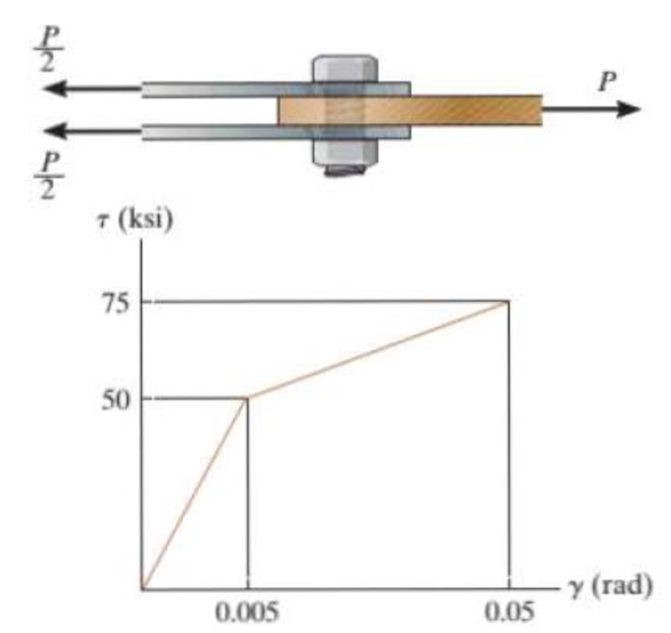
The lap joint is connected together using a 1.25 in. diameter boll. If the holt is made from a material having a shear stress-strain diagram that is approximated as shown, determine the shear strain developed in the shear plane of the bolt when P = 15 kip.
Probs. 8-25/26
Expert Solution & Answer
Want to see the full answer?
Check out a sample textbook solution
Students have asked these similar questions
8-27. The lap joint is connected together using a 30 mm
diameter bolt. If the bolt is made from a material having a
shear stress-strain diagram that is approximated as shown,
determine the permanent shear strain in the shear plane of
the bolt when the applied force P- 680 kN is removed.
7 (MPa)
525
350
(rad)
0.005
0.05
F8-16. A 20-mm-wide block is bonded to rigid plates at its
top and bottom. When the force Pis applied the block deforms
into the shape shown by the dashed line. If a-3 mm and P is
released, determine the permanent shear strain in the block.
т (MPa)
-150 mm-
3 mm
130
150 mm
y (rad)
0.005
7-35. The two members used in the construction of an
aircraft fuselage are joined together using a 30° fish-mouth
weld. Determine the average normal and average shear
stress on the plane of each weld. Assume each inclined
plane supports a horizontal force of 2 kN.
375 mm 30
4 kN
4 kN
25 mm
30
Chapter 8 Solutions
Statics and Mechanics of Materials (5th Edition)
Ch. 8.4 - Define a homogeneous material.Ch. 8.4 - Prob. 2FPCh. 8.4 - Prob. 3FPCh. 8.4 - Prob. 4FPCh. 8.4 - Prob. 5FPCh. 8.4 - As the temperature increases the modulus of...Ch. 8.4 - Prob. 7FPCh. 8.4 - Prob. 8FPCh. 8.4 - Prob. 9FPCh. 8.4 - Prob. 10FP
Ch. 8.4 - The material for the 50-mm-long specimen has the...Ch. 8.4 - If the elongation of wire BC is 0.2 mm after the...Ch. 8.4 - A tension test was performed on a steel specimen...Ch. 8.4 - Data taken from a stressstrain test for a ceramic...Ch. 8.4 - Data taken from a stressstrain test for a ceramic...Ch. 8.4 - Prob. 4PCh. 8.4 - The stress-strain diagram for a steel alloy having...Ch. 8.4 - Prob. 6PCh. 8.4 - The rigid beam is supported by a pin at C and an...Ch. 8.4 - The rigid beam is supported by a pin at C and an...Ch. 8.4 - Prob. 9PCh. 8.4 - The stressstrain diagram for an aluminum alloy...Ch. 8.4 - The stressstrain diagram for an aluminum alloy...Ch. 8.4 - Prob. 12PCh. 8.4 - A bar having a length of 5 in. and cross-sectional...Ch. 8.4 - The rigid pipe is supported by a pin at A and an...Ch. 8.4 - The rigid pipe is supported by a pin at A and an...Ch. 8.4 - Prob. 16PCh. 8.4 - The rigid beam is supported by a pin at C and an...Ch. 8.4 - Prob. 18PCh. 8.4 - Prob. 19PCh. 8.6 - A 100 mm long rod has a diameter of 15 mm. If an...Ch. 8.6 - A solid circular rod that is 600 mm long and 20 mm...Ch. 8.6 - Prob. 15FPCh. 8.6 - Prob. 16FPCh. 8.6 - The acrylic plastic rod is 200 mm long and 15 mm...Ch. 8.6 - The plug has a diameter of 30 mm and fits within a...Ch. 8.6 - The elastic portion of the stress-strain diagram...Ch. 8.6 - The elastic portion of the stress-strain diagram...Ch. 8.6 - The brake pads for a bicycle tire arc made of...Ch. 8.6 - The lap joint is connected together using a 1.25...Ch. 8.6 - The lap joint is connected together using a 1.25...Ch. 8.6 - Prob. 27PCh. 8.6 - The shear stress-strain diagram for an alloy is...Ch. 8.6 - Prob. 29PCh. 8 - The elastic portion of the tension stress-strain...Ch. 8 - Prob. 2RPCh. 8 - Prob. 3RPCh. 8 - Prob. 4RPCh. 8 - Prob. 5RPCh. 8 - Prob. 6RPCh. 8 - The stress-strain diagram for polyethylene, which...Ch. 8 - The pipe with two rigid caps attached to its ends...Ch. 8 - Prob. 9RPCh. 8 - Prob. 10RP
Knowledge Booster


Learn more about
Need a deep-dive on the concept behind this application? Look no further. Learn more about this topic, mechanical-engineering and related others by exploring similar questions and additional content below.Similar questions
- The lap joint is connected together using a 1.25 in. diameter bolt. If the bolt is made from a material having a shear stress–strain diagram that is approximated as shown, determine the shear strain developed in the shear plane of the bolt when P = 75 kip.arrow_forwardThe rectangular plate is subjected to the deformation shown by the dashed line. Assume a - 575 mm, Ax- 1.8 mm, and Ay- 2.0 mm. Determine the shear strains Vxy and Yxy at point A. Answers: Vxy = Yxy" 7887 -006604 prad uradarrow_forward*2-13. The piece of rubber is originally rectangular. Determine the average shear Yzy at A if the corners B and D are subjected to the displacements that cause the rubber to distort as shown by the dashed lines. Prob. 2-13 3 mm- y D 400 mm AK -300 mm- C B 2 mm Xarrow_forward
- *R7-8. The square plate is deformed into the shape shown by the dashed lines. If DC has a normal strain e,-0.004, DA has a normal strain e,-0.005 and at D, yay- 0.02 rad, determine the shear strain at point E with respect to the x' and y' axes. 600 mm- B' 600 mmarrow_forwardThe lap joint is connected together using a 30 mm diameter bolt. If the bolt is made from a material having a shear stress-strain diagram that is approximated as shown, determine the permanent shear strain in the shear plane of the bolt when the applied force P =750 kN is removed.arrow_forward7-51. The two steel members are joined together using a 30° scarf weld. Determine the average normal and average shear stress resisted in the plane of the weld. 15 kN 20 mm 30 40 mm 15 kNarrow_forward
- The board is subjected to a tensile force of 200 lb. Determine the average normal and average shear stress in the wood fibers, which are oriented along plane a–a at 20° with the axis of the board.arrow_forwardThe piece of rubber was rectangular in shape before the application of loads which deformed it to the shape bounded by the dashed lines. Determine the shear strain at corner A. Also determine the normal strain along diagonal DB I 3 mm- 400 mm 300 mm- B 2 mmarrow_forward7-75. The square deforms into the position shown by the dashed lines Determine the shear strain at each of its corners, A, B, C, and D, relative to the x, y axes. Side D'B' remains horizontal. 3 mm 53 mm 50 mm 91.5 50 mm 8 mmarrow_forward
- P7-8. A loading causes the member to deform into the dashed shape. Explain how to determine the normal strains ECp and eAn. The displacement A and the lettered dimensions are known. B. -2 L-arrow_forwardThe strain at point A on the bracket has normal components 250x10-6 and 550x10-6 in x and y directions, respectively and shear component -600 x10-6 in x-y plane. Determine the absolute maximum shear strain in 10-6 unit.arrow_forwardThe long bolt passes through the 70.4-mm-thick plate. If the force in the bolt shank is 9.5 KN, then the average shear stress (MPa) along the cylindrical area of the plate defined by the section lines a-a is: O a. 0.00 O b. 21.00 O c. 2.39 O d. 4.77 O e. 1.19 18 mm b b 8 mm Time left 0:45:52 a 7 mm YouTube The wood beam has an allowable shear stress of 15 MPa, the maximum shear force V (kN) that can be lind to the cross section is:arrow_forward
arrow_back_ios
SEE MORE QUESTIONS
arrow_forward_ios
Recommended textbooks for you
 Elements Of ElectromagneticsMechanical EngineeringISBN:9780190698614Author:Sadiku, Matthew N. O.Publisher:Oxford University Press
 Mechanics of Materials (10th Edition)Mechanical EngineeringISBN:9780134319650Author:Russell C. HibbelerPublisher:PEARSON
 Thermodynamics: An Engineering ApproachMechanical EngineeringISBN:9781259822674Author:Yunus A. Cengel Dr., Michael A. BolesPublisher:McGraw-Hill Education
 Control Systems EngineeringMechanical EngineeringISBN:9781118170519Author:Norman S. NisePublisher:WILEY
 Mechanics of Materials (MindTap Course List)Mechanical EngineeringISBN:9781337093347Author:Barry J. Goodno, James M. GerePublisher:Cengage Learning
 Engineering Mechanics: StaticsMechanical EngineeringISBN:9781118807330Author:James L. Meriam, L. G. Kraige, J. N. BoltonPublisher:WILEY
Elements Of Electromagnetics
Mechanical Engineering
ISBN:9780190698614
Author:Sadiku, Matthew N. O.
Publisher:Oxford University Press
Mechanics of Materials (10th Edition)
Mechanical Engineering
ISBN:9780134319650
Author:Russell C. Hibbeler
Publisher:PEARSON
Thermodynamics: An Engineering Approach
Mechanical Engineering
ISBN:9781259822674
Author:Yunus A. Cengel Dr., Michael A. Boles
Publisher:McGraw-Hill Education
Control Systems Engineering
Mechanical Engineering
ISBN:9781118170519
Author:Norman S. Nise
Publisher:WILEY
Mechanics of Materials (MindTap Course List)
Mechanical Engineering
ISBN:9781337093347
Author:Barry J. Goodno, James M. Gere
Publisher:Cengage Learning
Engineering Mechanics: Statics
Mechanical Engineering
ISBN:9781118807330
Author:James L. Meriam, L. G. Kraige, J. N. Bolton
Publisher:WILEY
EVERYTHING on Axial Loading Normal Stress in 10 MINUTES - Mechanics of Materials; Author: Less Boring Lectures;https://www.youtube.com/watch?v=jQ-fNqZWrNg;License: Standard YouTube License, CC-BY