
Mechanics of Materials
11th Edition
ISBN: 9780137605460
Author: Russell C. Hibbeler
Publisher: Pearson Education (US)
expand_more
expand_more
format_list_bulleted
Concept explainers
Videos
Textbook Question
Chapter 8.1, Problem 9P
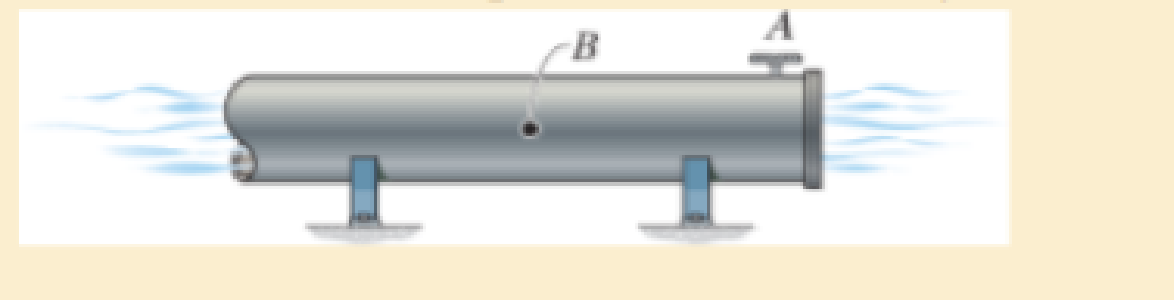
The steel water pipe has an inner diameter of 12 in. and a wall thickness of 0.25 in. If the valve A is closed and the water pressure is 300 psi, determine the longitudinal and hoop stress developed in the wall of the pipe at point B. Draw the state of stress on a volume element located on the wall.
Expert Solution & Answer

Trending nowThis is a popular solution!

Students have asked these similar questions
The tank of the air compressor is subjected to an internal pressure of 90 psi. If the inner diameter of the tank is 22 in., and the wall thickness is 0.25 in., determine the stress components acting at point A. Draw a volume element of the material at this point, and show the results on the element.
The thin-walled pipe has an inner diameter of 0.5 in. and a thickness of 0.025 in. If it is subjected to an internal pressure of 500 psi and the axial tension and torsional loadings shown, determine the principal stress at a point on the surface of the pipe.
In order to increase the strength of the pressure vessel, filament winding of the same material is wrapped around the circumference of the vessel as shown. If the pretension in the filament is T and the vessel is subjected toan internal pressure p, determine the hoop stresses in the filament and in the wall of the vessel. Use the free-body diagram shown, and assume the filament winding has a thickness t
and width w for a corresponding length L of the vessel.
Chapter 8 Solutions
Mechanics of Materials
Ch. 8.1 - If it is subjected to an internal pressure of p =...Ch. 8.1 - If it is subjected to an internal pressure of p =...Ch. 8.1 - The thin-walled cylinder can be supported in one...Ch. 8.1 - If the inner diameter of the tank is 22 in., and...Ch. 8.1 - Prob. 5PCh. 8.1 - 88. The steel water pipe has an inner diameter of...Ch. 8.1 - The steel water pipe has an inner diameter of 12...Ch. 8.2 - Fundamental Problems F81. Determine the normal...Ch. 8.2 - Show the results in a differential element at the...Ch. 8.2 - Determine the state of stress at point A on the...
Ch. 8.2 - Determine the magnitude of the load P that will...Ch. 8.2 - Determine the state of stress at point B. Show the...Ch. 8.2 - Determine the state of stress at point A on the...Ch. 8.2 - Determine the state of stress at point A on the...Ch. 8.2 - Show the results in a differential element at the...Ch. 8.2 - The plate has a thickness of 20 mm and P acts...Ch. 8.2 - Plot the distribution of normal stress acting...Ch. 8.2 - Also, plot the normal-stress distribution over the...Ch. 8.2 - Determine the stress components at point A on the...Ch. 8.2 - Determine the stress components at point B on the...Ch. 8.2 - If it is subjected to the force system shown,...Ch. 8.2 - Neglect the weight of the block.Ch. 8.2 - Neglect the weight of the block.Ch. 8.2 - He is supported uniformly by two bars, each having...Ch. 8.2 - Specify the region to which this load can be...Ch. 8.2 - The pins at C and D are at the same location as...Ch. 8.2 - If the force at the ram on the clamp at D is P= 8...Ch. 8.2 - Determine the maximum ram force P that can be...Ch. 8.2 - and an outer radius of 3.00 in. If the face of the...Ch. 8 - If it supports a cable loading of 800 lb,...Ch. 8 - Determine the state of stress at point E on the...Ch. 8 - Determine the state of stress at point F on the...Ch. 8 - The suspender arm AE has a square cross-sectional...Ch. 8 - If the cross section of the femur at section aa...Ch. 8 - If it has a mass of 5 kg/m, determine the largest...Ch. 8 - and is used to support the vertical reactions of...Ch. 8 - and is used to support the vertical reactions of...
Additional Engineering Textbook Solutions
Find more solutions based on key concepts
A 20-lb force is applied to the control rod AB as shown. Knowing that the length of the rod is 9 in. and that t...
Statics and Mechanics of Materials
What is the importance of modeling in engineering? How are the mathematical models for engineering processes pr...
HEAT+MASS TRANSFER:FUND.+APPL.
Comprehension Check 7-14
The power absorbed by a resistor can be given by P = I2R, where P is power in units of...
Thinking Like an Engineer: An Active Learning Approach (3rd Edition)
Define or describe each type of fluid: (a) viscoelastic fluid (b) pseudoplastic fluid (c) dilatant fluid (d) Bi...
Fluid Mechanics: Fundamentals and Applications
6–1C A mechanic claims to have developed a car engine that runs on water instead of gasoline. What is your resp...
Thermodynamics: An Engineering Approach
CONCEPT QUESTIONS
15.CQ3 The ball rolls without slipping on the fixed surface as shown. What is the direction ...
Vector Mechanics for Engineers: Statics and Dynamics
Knowledge Booster


Learn more about
Need a deep-dive on the concept behind this application? Look no further. Learn more about this topic, mechanical-engineering and related others by exploring similar questions and additional content below.Similar questions
- Air is pumped into the steel thin-walled pressure vessel at C. If the ends of the vessel are closed using two pistons connected by a rod AB, determine the increase in the diameter of the pressure vessel when the internal gage pressure is 5 MPa. Also, what is the tensile stress in rod AB if it has a diameter of 100 mm? The inner radius of the vessel is 400 mm, and its thickness is 10 mm. Est = 200 GPa and nst = 0.3.arrow_forwardQ1/ The steel water pipe has an inner diameter of 12 in. and wall thickness of 0.25 in. If the water pressure is 400 psi, determine the longitudinal and hoop stress developed in the wall when (a) the valve A is opened and (b) the valve A is closed. Also draw the state of stress on a volume element located at the wall for both cases.arrow_forwardDetermine the normal stress and shear stress acting on the inclined plane AB. Sketch the result on the sectioned element.arrow_forward
- The steel bracket is used to connect the ends of two cables. If the applied force P = 1.50 kip, determine the maximum normal stress in the bracket. Assume the bracket is a rod having a diameter of 1.5 in.arrow_forwardAir pressure in the cylinder is increased by exerting forces P = 2 kN on the two pistons, each having a radius of 45 mm. If the cylinder has a wall thickness of 2 mm, determine the state of stress in the wall of the cylinder.arrow_forwardThe spherical gas tank is fabricated by bolting together two hemispherical thin shells of thickness 30 mm. The gas contained in the tank is under a gauge pressure of 2.5 MPa. If the tank has an inner diameter of 8 m and is sealed with 900 bolts each 20 mm in diameter, determine the normal stress developed in the wall of the tank.arrow_forward
- The rotor shaft of the helicopter is subjected to the tensile force and torque shown when the rotor blades provide the lifting force to suspend the helicopter at midair. If the shaft has a diameter of 6 in., determine the principal stresses and maximum in-plane shear stress at a point located on the surface of the shaft.arrow_forwardA pressure-vessel head is fabricated by welding the circular plate to the end of the vessel as shown. If the vessel sustains an internal pressure of 450 kPa, determine the average shear stress in the weld and the state of stress in thewall of the vessel.arrow_forwardDetermine the maximum average shear stress developed in the 30-mm-diameter pin.arrow_forward
- 4. The steel water pipe has an inner diameter of 100 mm and wall thickness 5 mm. If the flow of water within the pipe in Figure 4 is stopped due to the closing of a valve, determine the longitudinal and hoop stress developed at point A. Draw the state of stress on a volume element located on the wall A. 5 mm valve AI pressure 0.5 Mpa 50 mm Figure 4arrow_forwardThe wide-flange beam is subjected to the 50-kN force. Determine the principal stresses in the beam at point A located on the web at the bottom of the upper flange. Although it is not very accurate, use the shear formula tocalculate the shear stress.arrow_forwardThe gas storage tank is fabricated by bolting together two half cylindrical thin shells and two hemispherical shells as shown. If the tank wall has a thickness of 50 mm for cylindrical and hemispherical shells, The bolts were installed as 40 bolts/meter. The tank and the 25 mm diameter bolts are made from material having an allowable normal stress of 150 MPa and 250 MPa, respectively. The tank has an inner diameter of 4 m. What is the maximum pressure that tank can contain.arrow_forward
arrow_back_ios
SEE MORE QUESTIONS
arrow_forward_ios
Recommended textbooks for you
 Elements Of ElectromagneticsMechanical EngineeringISBN:9780190698614Author:Sadiku, Matthew N. O.Publisher:Oxford University Press
 Mechanics of Materials (10th Edition)Mechanical EngineeringISBN:9780134319650Author:Russell C. HibbelerPublisher:PEARSON
 Thermodynamics: An Engineering ApproachMechanical EngineeringISBN:9781259822674Author:Yunus A. Cengel Dr., Michael A. BolesPublisher:McGraw-Hill Education
 Control Systems EngineeringMechanical EngineeringISBN:9781118170519Author:Norman S. NisePublisher:WILEY
 Mechanics of Materials (MindTap Course List)Mechanical EngineeringISBN:9781337093347Author:Barry J. Goodno, James M. GerePublisher:Cengage Learning
 Engineering Mechanics: StaticsMechanical EngineeringISBN:9781118807330Author:James L. Meriam, L. G. Kraige, J. N. BoltonPublisher:WILEY
Elements Of Electromagnetics
Mechanical Engineering
ISBN:9780190698614
Author:Sadiku, Matthew N. O.
Publisher:Oxford University Press
Mechanics of Materials (10th Edition)
Mechanical Engineering
ISBN:9780134319650
Author:Russell C. Hibbeler
Publisher:PEARSON
Thermodynamics: An Engineering Approach
Mechanical Engineering
ISBN:9781259822674
Author:Yunus A. Cengel Dr., Michael A. Boles
Publisher:McGraw-Hill Education
Control Systems Engineering
Mechanical Engineering
ISBN:9781118170519
Author:Norman S. Nise
Publisher:WILEY
Mechanics of Materials (MindTap Course List)
Mechanical Engineering
ISBN:9781337093347
Author:Barry J. Goodno, James M. Gere
Publisher:Cengage Learning
Engineering Mechanics: Statics
Mechanical Engineering
ISBN:9781118807330
Author:James L. Meriam, L. G. Kraige, J. N. Bolton
Publisher:WILEY
Pressure Vessels Introduction; Author: Engineering and Design Solutions;https://www.youtube.com/watch?v=Z1J97IpFc2k;License: Standard youtube license