
Concept explainers
Videos
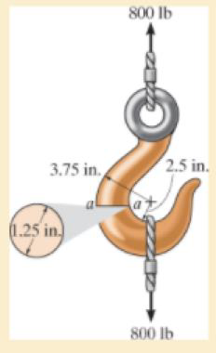
If it supports a cable loading of 800 lb, determine the maximum normal stress at section a–a and sketch the stress distribution acting over the cross section. Use the curved-beam formula to calculate the bending stress.
The maximum tensile stress
The maximum compressive stress
To sketch:
The stress distribution over the cross section.
Answer to Problem 1RP
The maximum tensile stress
The maximum compressive stress
Explanation of Solution
Given information:
The force in the cable is 800 lb.
Diameter of the circular is 1.25 in.
Calculation:
Expression to find the location of neutral
Here, R is the location of neutral axis, A is the cross sectional area of the member, r is the arbitrary position, and
Determine the radius
Here, d is the diameter of the circular cross section.
Substitute 1.25 in. for d in Equation (2).
Determine the area
Here, r is the radius of the circular cross section.
Substitute 0.625 in. for r in Equation (3).
Determine the value of
Here, c is the radius of cross section and
Find the distance measured from the center of curvature to the centroid of the cross section
Substitute 0.625 in. for c and 3.125 in. for
Substitute
Sketch the cross section of eye hook as shown in Figure 1.
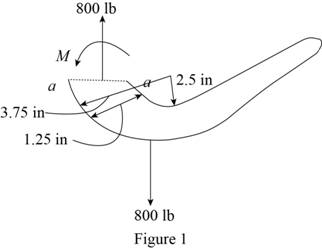
Let the moment acting at the section be M.
Express to the value of M as shown below:
Here, F is the load and R is the radius.
Determine the bending stress
Here, M is the applied moment and P is the applied load.
Substitute
Determine the maximum tensile stress
Hence, the maximum tensile stress
Determine the maximum compressive stress
Substitute
Hence, the maximum compressive stress
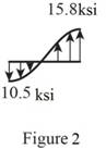
Sketch the stress distribution (tensile and compressive stress) along the cross section as shown in Figure 2.
Want to see more full solutions like this?
Chapter 8 Solutions
Mechanics of Materials


- If P = 3 kN, determine the bending stress at points A, B, and C of the cross section at section a–a. Using these results, sketch the stress distribution on section a–a.arrow_forwardIf the internal moment acting on the cross-section is 800 N.m, determine the maximum tensile and compressive bending stresses acting in the beam. Sketch the stress-distribution acting on the cross-section.arrow_forwardThe beam has the rectangular cross section shown. If w = 1 kN>m, determine the maximum bending stress in the beam. Sketch the stress distribution acting over the cross section.arrow_forward
- The bar has a thickness of 0.5 in. and is subjected to a moment of 600 lb # ft. Determine the maximum bending stress in the bar.arrow_forwardDetermine the maximum shear stress in the T-beam at section C. Show the result on a volume element at this point.arrow_forwardThe shaft is supported by smooth journal bearings at A and B that only exert vertical reactions on the shaft. If d = 90 mm, determine the absolute maximum bending stress in the beam, and sketch the stress distribution acting over the cross section.arrow_forward
- An A-36 steel strap having a thickness of 10 mm and a width of 20 mm is bent into a circular arc of radius r = 10 m. Determine the maximum bending stress in the strap.arrow_forward(d) How far is the maximum compressive bending stress located from support A? (Consider x=0 at support A) (e) Calculate the maximum shear stress. (Express the stress in Pa or MPa) and determine the location of maximum shear stress with respect to neutral axis. (f) How far is the maximum shear stress located located from support A? (Consider x=0 at support A)arrow_forwardThe aluminum strut has a cross-sectional area in the form of a cross. It is subjected tothe Moment M = 8 KN.m. (i) Determine the bending stress acting at points A and B; (ii)Determine the maximum bending stress in the beam and sketch a three dimensional view of thestress distribution acting over the entire cross-sectional area.arrow_forward
- The shaft is supported by a smooth thrust bearing at A and smooth journal bearing at C. If d = 3 in., determine the absolute maximum bending stress in the shaft.arrow_forwardThe tapered beam supports the concentrated force P at its center. Determine the absolute maximum bending stress in the beam. The reactions at the supports are vertical.arrow_forwarddetermine the maximum bending stress at the section aa of the cable cutter handle applies 225 N force to the handles cross sectional area shown in the figurearrow_forward
 Elements Of ElectromagneticsMechanical EngineeringISBN:9780190698614Author:Sadiku, Matthew N. O.Publisher:Oxford University Press
 Mechanics of Materials (10th Edition)Mechanical EngineeringISBN:9780134319650Author:Russell C. HibbelerPublisher:PEARSON
 Thermodynamics: An Engineering ApproachMechanical EngineeringISBN:9781259822674Author:Yunus A. Cengel Dr., Michael A. BolesPublisher:McGraw-Hill Education
 Control Systems EngineeringMechanical EngineeringISBN:9781118170519Author:Norman S. NisePublisher:WILEY
 Mechanics of Materials (MindTap Course List)Mechanical EngineeringISBN:9781337093347Author:Barry J. Goodno, James M. GerePublisher:Cengage Learning
 Engineering Mechanics: StaticsMechanical EngineeringISBN:9781118807330Author:James L. Meriam, L. G. Kraige, J. N. BoltonPublisher:WILEY