
Mechanics of Materials
11th Edition
ISBN: 9780137605460
Author: Russell C. Hibbeler
Publisher: Pearson Education (US)
expand_more
expand_more
format_list_bulleted
Concept explainers
Videos
Textbook Question
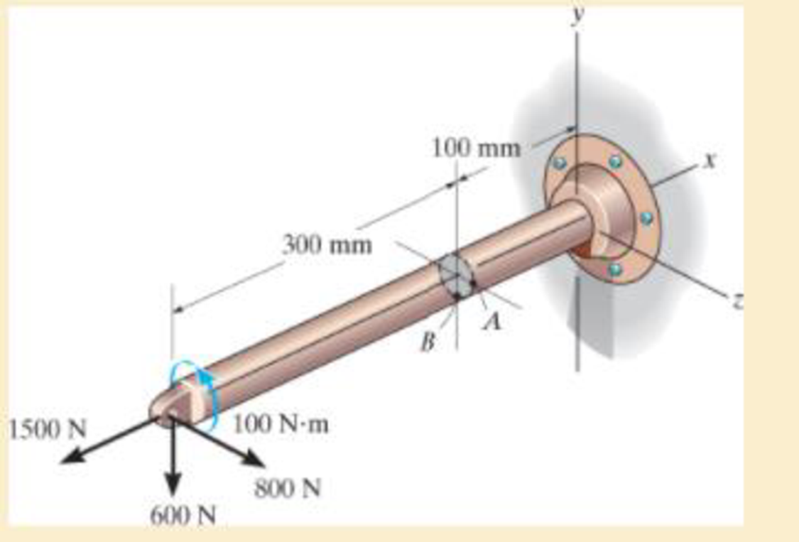
Chapter 8.2, Problem 40P
If it is subjected to the force system shown, determine the stress components that act at point A, and show the results on a volume element located at this point.
Expert Solution & Answer

Learn your wayIncludes step-by-step video

schedule15:00
Students have asked these similar questions
The rod has a diameter of 40 mm. If it is subjected to the force system shown, determine the stress components that act at point A, and show the results on a volume element located at this point.
Determine the shortest distance d to the edge of the plate at which the force P can be applied so that it produces no compressive stresses in the plate at section a–a. The plate has a thickness of 10 mm and P acts along the centerline of this thickness.
The sign is subjected to the uniform wind loading. Determine the stress components at points A and B on the 100-mm-diameter supporting post. Show the results on a volume element located at each of these points.
Chapter 8 Solutions
Mechanics of Materials
Ch. 8.1 - If it is subjected to an internal pressure of p =...Ch. 8.1 - If it is subjected to an internal pressure of p =...Ch. 8.1 - The thin-walled cylinder can be supported in one...Ch. 8.1 - If the inner diameter of the tank is 22 in., and...Ch. 8.1 - Prob. 5PCh. 8.1 - 88. The steel water pipe has an inner diameter of...Ch. 8.1 - The steel water pipe has an inner diameter of 12...Ch. 8.2 - Fundamental Problems F81. Determine the normal...Ch. 8.2 - Show the results in a differential element at the...Ch. 8.2 - Determine the state of stress at point A on the...
Ch. 8.2 - Determine the magnitude of the load P that will...Ch. 8.2 - Determine the state of stress at point B. Show the...Ch. 8.2 - Determine the state of stress at point A on the...Ch. 8.2 - Determine the state of stress at point A on the...Ch. 8.2 - Show the results in a differential element at the...Ch. 8.2 - The plate has a thickness of 20 mm and P acts...Ch. 8.2 - Plot the distribution of normal stress acting...Ch. 8.2 - Also, plot the normal-stress distribution over the...Ch. 8.2 - Determine the stress components at point A on the...Ch. 8.2 - Determine the stress components at point B on the...Ch. 8.2 - If it is subjected to the force system shown,...Ch. 8.2 - Neglect the weight of the block.Ch. 8.2 - Neglect the weight of the block.Ch. 8.2 - He is supported uniformly by two bars, each having...Ch. 8.2 - Specify the region to which this load can be...Ch. 8.2 - The pins at C and D are at the same location as...Ch. 8.2 - If the force at the ram on the clamp at D is P= 8...Ch. 8.2 - Determine the maximum ram force P that can be...Ch. 8.2 - and an outer radius of 3.00 in. If the face of the...Ch. 8 - If it supports a cable loading of 800 lb,...Ch. 8 - Determine the state of stress at point E on the...Ch. 8 - Determine the state of stress at point F on the...Ch. 8 - The suspender arm AE has a square cross-sectional...Ch. 8 - If the cross section of the femur at section aa...Ch. 8 - If it has a mass of 5 kg/m, determine the largest...Ch. 8 - and is used to support the vertical reactions of...Ch. 8 - and is used to support the vertical reactions of...
Additional Engineering Textbook Solutions
Find more solutions based on key concepts
Determine the force in each member of the truss and state if the members are in tension or compression. Prob. 6...
Engineering Mechanics: Statics
Comprehension Check 7-16
A basketball has a diameter of approximately 27 centimeters [cm]. Find the spherical v...
Thinking Like an Engineer: An Active Learning Approach (3rd Edition)
What parts are included in the vehicle chassis?
Automotive Technology: Principles, Diagnosis, and Service (5th Edition)
The free body diagram of the ring at A. The magnitude of force in each cable.
Engineering Mechanics: Statics & Dynamics (14th Edition)
Determine the slope and deflection of end A of the cantilevered beam. E = 200 GPa and I = 65.0(106) mm4. F121
Mechanics of Materials
If the powder burns at a constant rate of 20 g/s such as that the exhaust gases always exert a force having a c...
Engineering Mechanics: Dynamics (14th Edition)
Knowledge Booster


Learn more about
Need a deep-dive on the concept behind this application? Look no further. Learn more about this topic, mechanical-engineering and related others by exploring similar questions and additional content below.Similar questions
- The solid bar has a diameter of 50 mm. The two forces and the torque Tx are acting at the origin of the x-y-z coordinate system which is coincident with the centroid of the cross-section of the bar; the 1800 N force is acting in the y-z plane and torque T is acting about the x-axis. Determine the state of stress at points A and B, and show the respective stress components acting on differential elements located at these two points. {30 marks} 200 mm y 200 mm B. 1200 N T= 40 N.m 1800 Narrow_forwardDetermine the normal stress and shear stress acting on the inclined plane AB. Solve the problem using the stress transformation equations. Show the results on the sectional element.arrow_forwardThe solid bar has a diameter of 50 mm. The two forces and the torque Tx are acting at the origin of the x-y-z coordinate system which is coincident with the centroid of the cross-section of the bar; the 1800 N force is acting in the y-z plane and torque Tx is acting about the x-axis. Determine the state of stress at points A and B, and show the respective stress components acting on differential elements located at these two points. 200 mm/ y 200 mm 1200 N Tx = 40 N.m %3D 1800 Narrow_forward
- The plate has a width of 0.5 m. If the stress distribution at the support varies as shown, determine the force P applied to the plate and the distance d to where it is applied.arrow_forwardThe 1-in.-diameter rod is subjected to the loads shown. Determine the state of stress at point B, and show the results on a differential volume element located at this point.arrow_forwardThe bar has a diameter of 40 mm. Determine the state of stress at point A and show the results on a differential volume element located at this point.arrow_forward
- The solid rod is subjected to the loading shown. Determine the state of stress at point B, and show the results on a differential volume element at this point.arrow_forwardThe box beam is subjected to the 26-kN force that is applied at the center of its width, 75 mm from each side. Determine the principal stresses at point A and show the results in an element located at this point. Use the shear formula to calculate the shear stress.arrow_forwardThe bent shaft is fixed in the wall at A. If a force F is applied at B (the force is acting on the plane parallel to the x-o-y plane). Take F = 54 N and 0 = 45°. 1. Determine the internal forces acting on the section containing points D and E 2. Determine the normal stress component acting at point E 3. Determine the shear stress component developed at point E 4. Draw the state of stress on a volume element (stress element) located at point E 5. Determine the principal stresses acting at point E by constructing Mohr's circle A 150 mm E 200 mm 30 mm 75 mm B Farrow_forward
- The drill is jammed in the wall and is subjected to the torque and force shown. Determine the state of stress at point B on the cross section of the drill bit at section a–a.arrow_forwardDetermine the normal stress and shear stress acting on the inclined plane AB. Solve the problem using the method of equilibrium described in Sec.arrow_forwardThe 1-in.-diameter rod is subjected to the loads shown. Determine the state of stress at point A, and show the results on a differential volume element located at this point.arrow_forward
arrow_back_ios
SEE MORE QUESTIONS
arrow_forward_ios
Recommended textbooks for you
 Elements Of ElectromagneticsMechanical EngineeringISBN:9780190698614Author:Sadiku, Matthew N. O.Publisher:Oxford University Press
 Mechanics of Materials (10th Edition)Mechanical EngineeringISBN:9780134319650Author:Russell C. HibbelerPublisher:PEARSON
 Thermodynamics: An Engineering ApproachMechanical EngineeringISBN:9781259822674Author:Yunus A. Cengel Dr., Michael A. BolesPublisher:McGraw-Hill Education
 Control Systems EngineeringMechanical EngineeringISBN:9781118170519Author:Norman S. NisePublisher:WILEY
 Mechanics of Materials (MindTap Course List)Mechanical EngineeringISBN:9781337093347Author:Barry J. Goodno, James M. GerePublisher:Cengage Learning
 Engineering Mechanics: StaticsMechanical EngineeringISBN:9781118807330Author:James L. Meriam, L. G. Kraige, J. N. BoltonPublisher:WILEY
Elements Of Electromagnetics
Mechanical Engineering
ISBN:9780190698614
Author:Sadiku, Matthew N. O.
Publisher:Oxford University Press
Mechanics of Materials (10th Edition)
Mechanical Engineering
ISBN:9780134319650
Author:Russell C. Hibbeler
Publisher:PEARSON
Thermodynamics: An Engineering Approach
Mechanical Engineering
ISBN:9781259822674
Author:Yunus A. Cengel Dr., Michael A. Boles
Publisher:McGraw-Hill Education
Control Systems Engineering
Mechanical Engineering
ISBN:9781118170519
Author:Norman S. Nise
Publisher:WILEY
Mechanics of Materials (MindTap Course List)
Mechanical Engineering
ISBN:9781337093347
Author:Barry J. Goodno, James M. Gere
Publisher:Cengage Learning
Engineering Mechanics: Statics
Mechanical Engineering
ISBN:9781118807330
Author:James L. Meriam, L. G. Kraige, J. N. Bolton
Publisher:WILEY
Everything About COMBINED LOADING in 10 Minutes! Mechanics of Materials; Author: Less Boring Lectures;https://www.youtube.com/watch?v=N-PlI900hSg;License: Standard youtube license