
Mechanics of Materials
11th Edition
ISBN: 9780137605460
Author: Russell C. Hibbeler
Publisher: Pearson Education (US)
expand_more
expand_more
format_list_bulleted
Concept explainers
Videos
Textbook Question
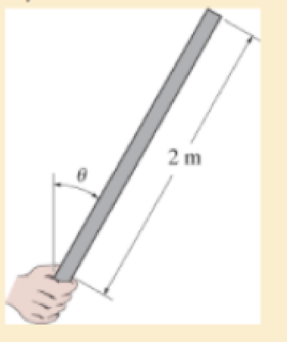
Chapter 8, Problem 6RP
If it has a mass of 5 kg/m, determine the largest angle θ, measured from the vertical, at which it can be supported before it is subjected to a tensile stress along its axis near the grip.
Expert Solution & Answer
Want to see the full answer?
Check out a sample textbook solution
Students have asked these similar questions
Determine the internal normal force at point F in the frame. The crate weighs 151 lb.
4 ft
1.5 ft 1.5 ft 1.5 ft 1.5 ft
O
B
F
C E
D
0.4 ft
Determine the tensile force of the rope.
If the block is subjected to the centrally applied
force of 600 kN. Determine the cross-sectional area where the
load is applied.
Chapter 8 Solutions
Mechanics of Materials
Ch. 8.1 - If it is subjected to an internal pressure of p =...Ch. 8.1 - If it is subjected to an internal pressure of p =...Ch. 8.1 - The thin-walled cylinder can be supported in one...Ch. 8.1 - If the inner diameter of the tank is 22 in., and...Ch. 8.1 - Prob. 5PCh. 8.1 - 88. The steel water pipe has an inner diameter of...Ch. 8.1 - The steel water pipe has an inner diameter of 12...Ch. 8.2 - Fundamental Problems F81. Determine the normal...Ch. 8.2 - Show the results in a differential element at the...Ch. 8.2 - Determine the state of stress at point A on the...
Ch. 8.2 - Determine the magnitude of the load P that will...Ch. 8.2 - Determine the state of stress at point B. Show the...Ch. 8.2 - Determine the state of stress at point A on the...Ch. 8.2 - Determine the state of stress at point A on the...Ch. 8.2 - Show the results in a differential element at the...Ch. 8.2 - The plate has a thickness of 20 mm and P acts...Ch. 8.2 - Plot the distribution of normal stress acting...Ch. 8.2 - Also, plot the normal-stress distribution over the...Ch. 8.2 - Determine the stress components at point A on the...Ch. 8.2 - Determine the stress components at point B on the...Ch. 8.2 - If it is subjected to the force system shown,...Ch. 8.2 - Neglect the weight of the block.Ch. 8.2 - Neglect the weight of the block.Ch. 8.2 - He is supported uniformly by two bars, each having...Ch. 8.2 - Specify the region to which this load can be...Ch. 8.2 - The pins at C and D are at the same location as...Ch. 8.2 - If the force at the ram on the clamp at D is P= 8...Ch. 8.2 - Determine the maximum ram force P that can be...Ch. 8.2 - and an outer radius of 3.00 in. If the face of the...Ch. 8 - If it supports a cable loading of 800 lb,...Ch. 8 - Determine the state of stress at point E on the...Ch. 8 - Determine the state of stress at point F on the...Ch. 8 - The suspender arm AE has a square cross-sectional...Ch. 8 - If the cross section of the femur at section aa...Ch. 8 - If it has a mass of 5 kg/m, determine the largest...Ch. 8 - and is used to support the vertical reactions of...Ch. 8 - and is used to support the vertical reactions of...
Knowledge Booster


Learn more about
Need a deep-dive on the concept behind this application? Look no further. Learn more about this topic, mechanical-engineering and related others by exploring similar questions and additional content below.Similar questions
- The 20 mm diameter steel shaft AB is attached into the rigid wall at B and supported by a smooth bearing at A. The lever AC is welded to the end of the shaft. If the downward force P will produce a 50 mm vertical displacement at the free end of lever AC, determine the force P if G = 83 GPa.arrow_forwardThe post weighs 8 kN>m. Determine the internal normal force in the post as a function of x.arrow_forwardDetermine the magnitude of the pin force at A. Assume W = 900 Ib, a = 5.8 ft, b = 3.9 ft, r = 9 in. B W Answer: A = i Ibarrow_forward
- Determine the resultant force at pins A, B, and C on the three-member frame. Given: F = 40N, w = 10, L = 1.arrow_forwardThe small-block has a thickness of 0.5 in. If the stress distribution at the support developed by the load varies as shown, determine the force F applied to the block, and the distance d to where it is applied.arrow_forwardThe bracket is held to the wall using three A-36 steel bolts at B, C, and D. Each bolt has a diameter of 0.5 in. and an unstretched length of 2 in. If a force of 800 lb is placed on the bracket as shown,determine the force developed in each bolt. For the calculation, assume that the bolts carry no shear; rather, the vertical force of 800 lb is supported by the toe at A. Also, assume that the wall and bracket are rigid. A greatly exaggerated deformation of the bolts is shown.arrow_forward
- The bracket is held to the wall using three A-36 steel bolts at B, C, and D. Each bolt has a diameter of 0.5 in. and an unstretched length of 2 in. If a force of 800 lb is placed on the bracket as shown, determine the force developed in each bolt. For the calculation, assume that the bolts carry no shear; rather, the vertical force of 800 lb is supported by the toe at A. Also, assume that the wall and bracket are rigid. A greatly exaggerated deformation of the bolts is shown.arrow_forwardThe uniform bar, having a cross-sectional area of A and mass per unit length of m, is pinned at its center. If it is rotating in the horizontal plane at a constant angular rate of v, determine the average normal stress in the bar as a function of x.arrow_forwardIf a force of F = 350 N is applied to the handle of the toggle clamp, determine the resulting clamping force at A.arrow_forward
- Determine the normal stress and shear stress acting on the inclined plane AB. Solve the problem using the method of equilibrium described in Sec.arrow_forwardThe rigid bar AB and CD are supported by pins at A and D. the vertical rods are made of aluminum and bronze. Determine the vertical displacement of the point where the force P= 10 kips is applied. Neglect the weight of the members.arrow_forward
arrow_back_ios
arrow_forward_ios
Recommended textbooks for you
 Elements Of ElectromagneticsMechanical EngineeringISBN:9780190698614Author:Sadiku, Matthew N. O.Publisher:Oxford University Press
 Mechanics of Materials (10th Edition)Mechanical EngineeringISBN:9780134319650Author:Russell C. HibbelerPublisher:PEARSON
 Thermodynamics: An Engineering ApproachMechanical EngineeringISBN:9781259822674Author:Yunus A. Cengel Dr., Michael A. BolesPublisher:McGraw-Hill Education
 Control Systems EngineeringMechanical EngineeringISBN:9781118170519Author:Norman S. NisePublisher:WILEY
 Mechanics of Materials (MindTap Course List)Mechanical EngineeringISBN:9781337093347Author:Barry J. Goodno, James M. GerePublisher:Cengage Learning
 Engineering Mechanics: StaticsMechanical EngineeringISBN:9781118807330Author:James L. Meriam, L. G. Kraige, J. N. BoltonPublisher:WILEY
Elements Of Electromagnetics
Mechanical Engineering
ISBN:9780190698614
Author:Sadiku, Matthew N. O.
Publisher:Oxford University Press
Mechanics of Materials (10th Edition)
Mechanical Engineering
ISBN:9780134319650
Author:Russell C. Hibbeler
Publisher:PEARSON
Thermodynamics: An Engineering Approach
Mechanical Engineering
ISBN:9781259822674
Author:Yunus A. Cengel Dr., Michael A. Boles
Publisher:McGraw-Hill Education
Control Systems Engineering
Mechanical Engineering
ISBN:9781118170519
Author:Norman S. Nise
Publisher:WILEY
Mechanics of Materials (MindTap Course List)
Mechanical Engineering
ISBN:9781337093347
Author:Barry J. Goodno, James M. Gere
Publisher:Cengage Learning
Engineering Mechanics: Statics
Mechanical Engineering
ISBN:9781118807330
Author:James L. Meriam, L. G. Kraige, J. N. Bolton
Publisher:WILEY
EVERYTHING on Axial Loading Normal Stress in 10 MINUTES - Mechanics of Materials; Author: Less Boring Lectures;https://www.youtube.com/watch?v=jQ-fNqZWrNg;License: Standard YouTube License, CC-BY