
Fundamentals of Geotechnical Engineering (MindTap Course List)
5th Edition
ISBN: 9781305635180
Author: Braja M. Das, Nagaratnam Sivakugan
Publisher: Cengage Learning
expand_more
expand_more
format_list_bulleted
Concept explainers
Videos
Textbook Question
Chapter 8, Problem 8.20P
Refer to Figure 8.24. Determine the vertical stress increase, Δσ, at point A with the following values:
q1 = 100 kN/m x1 = 3 m z = 2 m
q2 = 200 kN/m x2 = 2 m
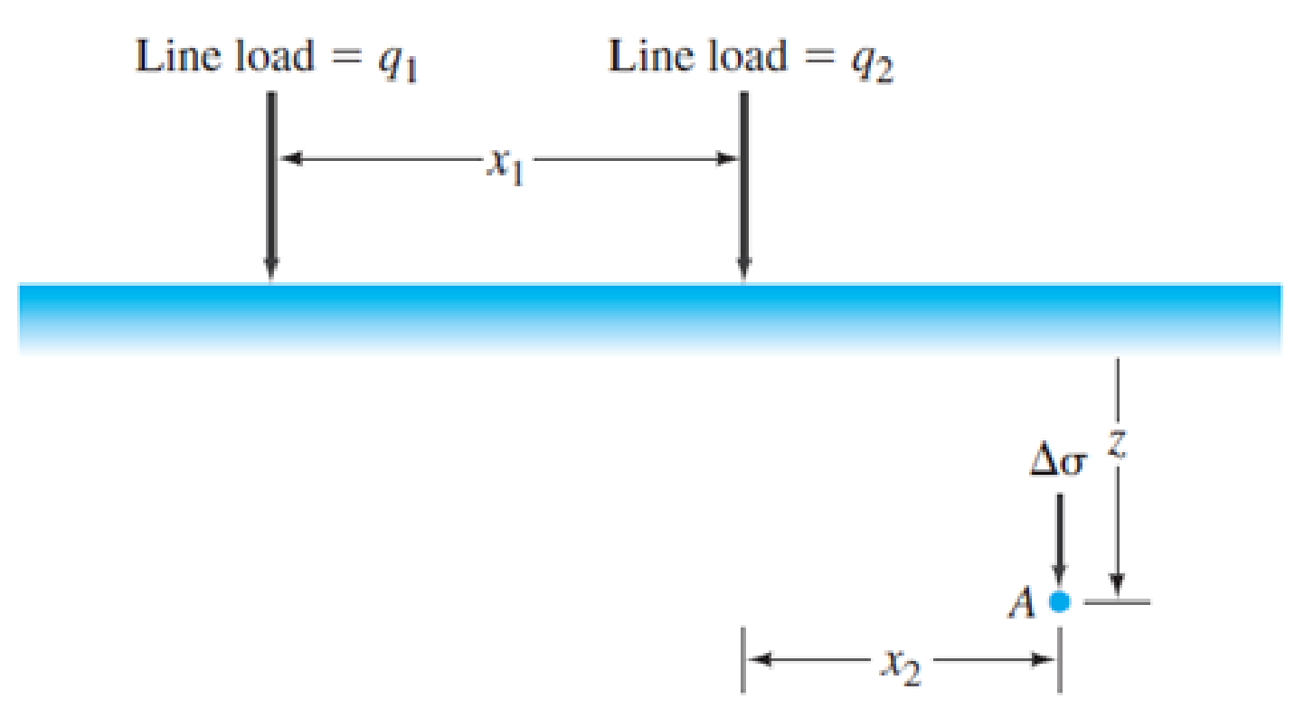
FIG. 8.24 Stress at a point due to two line loads
Expert Solution & Answer

Trending nowThis is a popular solution!

Students have asked these similar questions
Problem 6. [Concepts: Spatially varying average normal stress, and integration] The bar has a
cross-sectional area of 400(106) m². If it is subjected to a triangular axial distributed loading
along its length which is 0 at x = 0 and 9 kN/m at x = 1.5 m, and to two concentrated loads as
shown in the figure.
a) Determine the average normal stress in the bar as a function of x for 0
1. From the given figure below, determine the following:
a. Maximum shearing stress of the beam
b. Shearing stress 5 ft away from point A
c. Shearing stress 4 ft away from point B
Figure 1
18 kip / ft
14 in
10 kip / ft
A
8 in
20 ft
Constant thickness 2 inches
Consider a point in a structural member that is subjected to plane stress. Normal and shear stresses acting on horizontal and vertical
planes at the point are shown. If o = 18 ksi in the direction shown, determine the magnitude of the maximum in-plane shear stress at
%3D
the point.
15 ksi
4 ksi
11.2 ksi
15.5 ksi
13.6 ksi
18.6 ksi
17.3 ksi
O O O O O
Chapter 8 Solutions
Fundamentals of Geotechnical Engineering (MindTap Course List)
Ch. 8 - Prob. 8.1PCh. 8 - Prob. 8.2PCh. 8 - Prob. 8.3PCh. 8 - Prob. 8.4PCh. 8 - Prob. 8.5PCh. 8 - Prob. 8.6PCh. 8 - Prob. 8.7PCh. 8 - Prob. 8.8PCh. 8 - Prob. 8.9PCh. 8 - The soil profile at a site consists of 10 m of...
Ch. 8 - Prob. 8.11PCh. 8 - Prob. 8.12PCh. 8 - Prob. 8.13PCh. 8 - Prob. 8.14PCh. 8 - A sand has Gs = 2.66. Calculate the hydraulic...Ch. 8 - Prob. 8.16PCh. 8 - A point load of 1000 kN is applied at the ground...Ch. 8 - Point loads of magnitude 9, 18, and 27 kN act at...Ch. 8 - Refer to Figure 8.13. The magnitude of the line...Ch. 8 - Refer to Figure 8.24. Determine the vertical...Ch. 8 - Consider a circularly loaded flexible area on the...Ch. 8 - A flexible circular footing of radius R carries a...Ch. 8 - The plan of a flexible rectangular loaded area is...Ch. 8 - Refer to Figure 8.26. The circular flexible area...Ch. 8 - Refer to Figure 8.27. The flexible area is...Ch. 8 - Prob. 8.26CTPCh. 8 - Prob. 8.27CTP
Knowledge Booster


Learn more about
Need a deep-dive on the concept behind this application? Look no further. Learn more about this topic, civil-engineering and related others by exploring similar questions and additional content below.Similar questions
- Determine the normal stress developed at points A, B, and C. The diameter of each segment is indicated in the figure. (Note = 1 kip = 1,000 lbs) 1 in. 0.5 in. 0.5 in. B. 3 kip A |9 kip |8 kip | c 2 kiparrow_forwardUse Eq. (6.14) to determine the stress increase () at z = 10 ft below the center of the area described in Problem 6.5. 6.5 Refer to Figure 6.6, which shows a flexible rectangular area. Given: B1 = 4 ft, B2 = 6 ft, L1, = 8 ft, and L2 = 10 ft. If the area is subjected to a uniform load of 3000 lb/ft2, determine the stress increase at a depth of 10 ft located immediately below point O. Figure 6.6 Stress below any point of a loaded flexible rectangular areaarrow_forwardRefer to Figure 10.43. A strip load of q = 1450 lb/ft2 is applied over a width with B = 48 ft. Determine the increase in vertical stress at point A located z = 21 ft below the surface. Given x = 28.8 ft. Figure 10.43arrow_forward
- EB and FG are two planes inside a soil element ABCD as shown in Figure 10.50. Stress conditions on the two planes are Plane EB: EB = 25 kN/m2; EB = +10 kN/m2 Plane FG: FG = 10 kN/m2; FG = 5 kN/m2 (Note: Mohrs circle sign conventions for stresses are used above) Given ; = 25, determine: a. The maximum and minimum principal stresses b. The angle between the planes EB and FG c. The external stresses on planes AB and BC that would cause the above internal stresses on planes EB and FGarrow_forwardRepeat Problem 10.12 for q = 700 kN/m2, B = 8 m, and z = 4 m. In this case, point A is located below the centerline under the strip load. 10.12 Refer to Figure 10.43. A strip load of q = 1450 lb/ft2 is applied over a width with B = 48 ft. Determine the increase in vertical stress at point A located z = 21 ft below the surface. Given x = 28.8 ft. Figure 10.43arrow_forwardRefer to Figure 10.46. A flexible circular area of radius 6 m is uniformly loaded. Given: q = 565 kN/m2. Using Newmarks chart, determine the increase in vertical stress, z, at point A. Figure 10.46arrow_forward
- Figure 1a shows a concrete beam supported by twosolid circular columns. Column AB is made from steeland column CD is made from aluminium, see the stressstrain graphs in Figure 1b. The concrete beam issubjected to the load P as shown in Figure 1a.1. Determine the normal stress in column AB andcolumn CD. 2. Determine the relative change in angle of point Cto A in degrees. Given: P= 100KN L1= 3m L2= 2m L3= 1m dAB= 60mm dCD= 60mmarrow_forward05) If the applicd shear force V = 90 kN, Plot the intensity of the shear-stress distribution acting over the cross-sectional area in the member shown in Figure (5). %3D 75 mm 25 mm 75 min 25 mm Figure (5) 25 mmarrow_forward1. For the beam showing in the figure, consider section n-n and determine; (a) The largest shearing stress in that section (b) The shearing stress at point a. 0.3 m 40 nim 10 KN 12 imm 150 mm 12 mm 200 mm 15 inarrow_forward
- Q1: For the two dimensional state of stresses snown in tne rigure, Tina ine normal and shear stresses acting on plane A and show the results in a sketch. All stresses are in kN/m? A 42.5 24 19.6 80 Q2 Shown in Figure 1 is the two-dimensional state of stresses at a certain point within a soil mass. Determir the stresses acting on the horizontal and vertical planes passing through that point and show them in a sketi 65 kNIm? 20 Is kNIm?arrow_forwardThe simply supported beam shown in Fig. P.14.13 carries two symmetrically placed transverse loads, W. A rectangular strain gauge rosette positioned at the point P gave strain readings as follows: €, = -222×10 “, ep=-213x10-6, ɛ=45×10-6. Also the direct stress at P due to an external axial compressive load is 7 N/mm². Calculate the magnitude of the transverse load. Take E=31000 N/mm², v=0.2. Ans. W=98.1 kNarrow_forwardA beam shown on the figure is subjected to a uniform load of 5 kN/m. Determine the minimum shearing stress in MPa. The "x" distance on the beam makes the shear stress as small as possible. W=5 kN/m -4m- -50arrow_forward
arrow_back_ios
SEE MORE QUESTIONS
arrow_forward_ios
Recommended textbooks for you
 Fundamentals of Geotechnical Engineering (MindTap...Civil EngineeringISBN:9781305635180Author:Braja M. Das, Nagaratnam SivakuganPublisher:Cengage Learning
 Principles of Geotechnical Engineering (MindTap C...Civil EngineeringISBN:9781305970939Author:Braja M. Das, Khaled SobhanPublisher:Cengage Learning
 Principles of Foundation Engineering (MindTap Cou...Civil EngineeringISBN:9781305081550Author:Braja M. DasPublisher:Cengage Learning
Fundamentals of Geotechnical Engineering (MindTap...
Civil Engineering
ISBN:9781305635180
Author:Braja M. Das, Nagaratnam Sivakugan
Publisher:Cengage Learning
Principles of Geotechnical Engineering (MindTap C...
Civil Engineering
ISBN:9781305970939
Author:Braja M. Das, Khaled Sobhan
Publisher:Cengage Learning
Principles of Foundation Engineering (MindTap Cou...
Civil Engineering
ISBN:9781305081550
Author:Braja M. Das
Publisher:Cengage Learning
Stress Distribution in Soils GATE 2019 Civil | Boussinesq, Westergaard Theory; Author: Gradeup- GATE, ESE, PSUs Exam Preparation;https://www.youtube.com/watch?v=6e7yIx2VxI0;License: Standard YouTube License, CC-BY