
Principles of Geotechnical Engineering (MindTap Course List)
9th Edition
ISBN: 9781305970939
Author: Braja M. Das, Khaled Sobhan
Publisher: Cengage Learning
expand_more
expand_more
format_list_bulleted
Concept explainers
Videos
Textbook Question
Chapter 10, Problem 10.1CTP
EB and FG are two planes inside a soil element ABCD as shown in Figure 10.50.
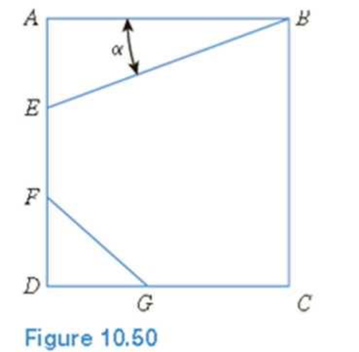
Stress conditions on the two planes are
Plane EB: σEB = 25 kN/m2; τEB = +10 kN/m2
Plane FG: σFG = 10 kN/m2; τFG = –5 kN/m2
(Note: Mohr’s circle sign conventions for stresses are used above)
Given α; = 25°, determine:
- a. The maximum and minimum principal stresses
- b. The angle between the planes EB and FG
- c. The external stresses on planes AB and BC that would cause the above internal stresses on planes EB and FG
Expert Solution & Answer

Trending nowThis is a popular solution!

Students have asked these similar questions
PROBLEM 2 (15 points):
The magnitude of stresses of the soil element represented by the figure below are oz = 250
kN
and t= 80 kN
m²
Oy = 180-
, and 0 = 25°, determine the following:
m2
a. Magnitudes of the principal stresses.
b. Normal stress on plane AB.
c. Shear stress on plane AB.
B
A
a. For the soil element shown in the figure, the magnitudes of the stresses are
kN
kN
Ox = 70
KN
Oy = 265
Try = 75
0 = 32°, draw Mohr's circle to
m2'
determine
• Normal and shear stresses on plane BD
• Magnitude of Principal Stresses
• Maximum shear stress and draw angle of maximum shear stress on the
soil element shown
b. If the soil element shown in above figure was extracted 17m below the ground
surface with y = 15, C = 1000 Pa and Ø = 22°, whether the soil will be
kN
safe against shear failure?
Oy
Tyx
Txy
Ox
Txy
B.
A
Tyx
Q.1
The state of stress at a point in a soil mass is eiven below, Determine the principal stresses and also the
octahedral normal and shear stresses.
50
30
25
Stress state
(soil)
30
40
25
kPa
25
25
08
Chapter 10 Solutions
Principles of Geotechnical Engineering (MindTap Course List)
Ch. 10 - Prob. 10.1PCh. 10 - Prob. 10.2PCh. 10 - Prob. 10.3PCh. 10 - Prob. 10.4PCh. 10 - Prob. 10.5PCh. 10 - Prob. 10.6PCh. 10 - Point loads of magnitude 125, 250, and 500 kN act...Ch. 10 - Refer to Figure 10.41. Determine the vertical...Ch. 10 - For the same line loads given in Problem 10.8,...Ch. 10 - Refer to Figure 10.41. Given: q2 = 3800 lb/ft, x1...
Ch. 10 - Refer to Figure 10.42. Due to application of line...Ch. 10 - Refer to Figure 10.43. A strip load of q = 1450...Ch. 10 - Repeat Problem 10.12 for q = 700 kN/m2, B = 8 m,...Ch. 10 - Prob. 10.14PCh. 10 - For the embankment shown in Figure 10.45,...Ch. 10 - Refer to Figure 10.46. A flexible circular area of...Ch. 10 - Refer to Figure 10.47. A flexible rectangular area...Ch. 10 - Refer to the flexible loaded rectangular area...Ch. 10 - Prob. 10.19PCh. 10 - Prob. 10.20PCh. 10 - Refer to Figure 10.48. If R = 4 m and hw = height...Ch. 10 - Refer to Figure 10.49. For the linearly increasing...Ch. 10 - EB and FG are two planes inside a soil element...Ch. 10 - A soil element beneath a pave ment experiences...
Knowledge Booster


Learn more about
Need a deep-dive on the concept behind this application? Look no further. Learn more about this topic, civil-engineering and related others by exploring similar questions and additional content below.Similar questions
- A soil element is shown in Figure 2.21. Determine the following using Mohr’s Circle: a. Maximum and minimum principal stressesb. Normal and shear stresses on plane ABarrow_forwardTopic 4:. A soil element is shown in Fig. 1. Determine the following (clearly show calculation procedures): a. Major principal stress b. Minor principal stress c. Normal and shear stress on plane EF d. Use rotation method to locate the normal and shear stress on the plane EF (plot the Mohr's circle by compass and locate normal and shear stress in Fig. 2, 0, = 45 kN/m? y T = 40 kN/m² D, ху C F 0, =150 kN/m? T = 40 kN/m? 22° ху E A В Fig.1. A stressed soil elementarrow_forwardA soil element is shown in Figure. Determine the following using Eqs.: a. Maximum and minimum principal stresses b. Normal and shear stresses on plane AB 26 kN/m2 8 kN/m2 17 &N/m2 8 kN/m2 450arrow_forward
- A soil element is shown in figure. Determine: a. Maximum and Minimum Principal stress. b.Normal and shear stress on plane ABarrow_forwardI want Normal stress developed in segment AB. A homogeneous bar with a cross-sectional area of 400 mm2 is attached to fixed supports as shown inthe figure. It is subjected to lateral forces P1 = 20 kN and P2 = 50 kN. Determine the normal stressdeveloped in segments AB and BC. Answer: σAB = 80.55 MPaarrow_forwardA Soil Element is shown in figure . Determine the Following: a. Maximum and Minimum Principal Stress b. Normal and Shear stresses on plane ABarrow_forward
- Please give me both answers right solution Soil mechanics, Mohr's circle An element of soil at the point of failure is represented as a square with effective stresses applied to it as normal (σ') and shear (τ) stresses. If (σ'a, τ) = (54,12) kPa and (σ'b,τ) = (20,12) kPa, determine the angle of shearing resistance for the soil φ' in degrees (°) to 1 decimal place.arrow_forwardA rectangular concrete slab, 4.a m. x 5.d m. is shown in Figure 3.5, rests on the surface of a soil mass. The load acting on the center of the slah is 1785KN. Determine: 'The soil stress just below the slab. ;) The vertical stress increase at point A. a. b. Plan A 4.5 m Cross Section 3.8 m A 3.1 m Figure 3.5 5.3 marrow_forwardHelp me pleasearrow_forward
- A rectangular concrete slab, 3m x 4.5m shown in Figure 05.12, rests on the surface of a soil mass. The load on the slab is 1620 kN.1.) Determine the soil stress below the slab2.) Determine the vertical stress increase at point A3.) Determine the vertical stress increase at point B.arrow_forward3 1. (a) An element of soil is subjected to the two-dimensional stresses shown in Figure Q1. 0, = 150 =-30 = 30 60° o, = 75 (All in kPa) Figure Q1 (1) Determine the normal and shear stresses on the P and Q planes which are orthogonal (ii) Determine the magnitudes and directions of the major and minor principal stresse (b) An undrained direct shear test with a hanger mass of 32 kg was performed on a sample of saturated clay. The plan dimensions of the shear box were 60 x 60 mm. The undrained shear strength of the clay is known to be Cu = 60 kPa. The critical state friction angle of the clay is known to be d'ern = 22°. What pore water pressure (u) in kPa, would the sample experience at the ultimate state? (c) Given that the pore pressure calculated from part (b) was negative, explain what this implies about the volume change that would have occurred to the sample (dilative or contractive) if the test was done under drained conditions.arrow_forwardProblem 2 A soil element is shown in the figure below. 26 kN/m2 8 kN/m2 B to + 17 kN/m2 8 kN/m2 45° Determine the following: (in kPa) a. Maximum Principal Stress b. Minimum Principal Stress c. Normal Stress on plane AB d. Shear Stress on plane ABarrow_forward
arrow_back_ios
SEE MORE QUESTIONS
arrow_forward_ios
Recommended textbooks for you
 Principles of Geotechnical Engineering (MindTap C...Civil EngineeringISBN:9781305970939Author:Braja M. Das, Khaled SobhanPublisher:Cengage Learning
Principles of Geotechnical Engineering (MindTap C...
Civil Engineering
ISBN:9781305970939
Author:Braja M. Das, Khaled Sobhan
Publisher:Cengage Learning
Stress Distribution in Soils GATE 2019 Civil | Boussinesq, Westergaard Theory; Author: Gradeup- GATE, ESE, PSUs Exam Preparation;https://www.youtube.com/watch?v=6e7yIx2VxI0;License: Standard YouTube License, CC-BY