
Principles of Geotechnical Engineering (MindTap Course List)
9th Edition
ISBN: 9781305970939
Author: Braja M. Das, Khaled Sobhan
Publisher: Cengage Learning
expand_more
expand_more
format_list_bulleted
Concept explainers
Videos
Textbook Question
Chapter 10, Problem 10.16P
Refer to Figure 10.46. A flexible circular area of radius 6 m is uniformly loaded. Given: q = 565 kN/m2. Using Newmark’s chart, determine the increase in vertical stress, Δσz, at point A.
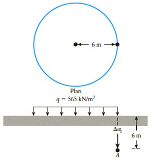
Figure 10.46
Expert Solution & Answer

Trending nowThis is a popular solution!

Students have asked these similar questions
Based on the figure given below, determine the stress increase at Points A, B and C at a depth of 2 m below the ground surface.
←3 m
5 m
A
9₁ = 90 kPa
B
C
Refer to the figure below.
Given:
q1 = 100kN/m, q2 = 200 kN/m
X1 = 3m, x2 = 3m, z = 3m
Determine the vertical stress increase at point A. (11.46)
Line load = 4,
Line load = q,
x1
A
10.12 Refer to Figure 10.42. A strip load of q = 43 kN/m2 is applied over a width,
B 11 m. Determine the increase in vertical stress at point A located z 4.6 m
below the surface. Given: x 8.2 m
В
q
load per unit area
Cengage Leaming 2014
Chapter 10 Solutions
Principles of Geotechnical Engineering (MindTap Course List)
Ch. 10 - Prob. 10.1PCh. 10 - Prob. 10.2PCh. 10 - Prob. 10.3PCh. 10 - Prob. 10.4PCh. 10 - Prob. 10.5PCh. 10 - Prob. 10.6PCh. 10 - Point loads of magnitude 125, 250, and 500 kN act...Ch. 10 - Refer to Figure 10.41. Determine the vertical...Ch. 10 - For the same line loads given in Problem 10.8,...Ch. 10 - Refer to Figure 10.41. Given: q2 = 3800 lb/ft, x1...
Ch. 10 - Refer to Figure 10.42. Due to application of line...Ch. 10 - Refer to Figure 10.43. A strip load of q = 1450...Ch. 10 - Repeat Problem 10.12 for q = 700 kN/m2, B = 8 m,...Ch. 10 - Prob. 10.14PCh. 10 - For the embankment shown in Figure 10.45,...Ch. 10 - Refer to Figure 10.46. A flexible circular area of...Ch. 10 - Refer to Figure 10.47. A flexible rectangular area...Ch. 10 - Refer to the flexible loaded rectangular area...Ch. 10 - Prob. 10.19PCh. 10 - Prob. 10.20PCh. 10 - Refer to Figure 10.48. If R = 4 m and hw = height...Ch. 10 - Refer to Figure 10.49. For the linearly increasing...Ch. 10 - EB and FG are two planes inside a soil element...Ch. 10 - A soil element beneath a pave ment experiences...
Knowledge Booster


Learn more about
Need a deep-dive on the concept behind this application? Look no further. Learn more about this topic, civil-engineering and related others by exploring similar questions and additional content below.Similar questions
- Use Eq. (6.14) to determine the stress increase () at z = 10 ft below the center of the area described in Problem 6.5. 6.5 Refer to Figure 6.6, which shows a flexible rectangular area. Given: B1 = 4 ft, B2 = 6 ft, L1, = 8 ft, and L2 = 10 ft. If the area is subjected to a uniform load of 3000 lb/ft2, determine the stress increase at a depth of 10 ft located immediately below point O. Figure 6.6 Stress below any point of a loaded flexible rectangular areaarrow_forwardRepeat Problem 10.12 for q = 700 kN/m2, B = 8 m, and z = 4 m. In this case, point A is located below the centerline under the strip load. 10.12 Refer to Figure 10.43. A strip load of q = 1450 lb/ft2 is applied over a width with B = 48 ft. Determine the increase in vertical stress at point A located z = 21 ft below the surface. Given x = 28.8 ft. Figure 10.43arrow_forward2. (10 pts) Refer to Figure 1. Due to application of line load q₁, the vertical stress increase at point A is 30 kN/m². Determine the magnitude of q1. PIEN 91 45° Figure 1 3 m A Aσ₂ 3 marrow_forward
- 10.12 Refer to Figure 10.42. A strip load of q = 43 kN/m? is applied over a width, B= 11 m. Determine the increase in vertical stress at point A located z = 4.6 m below the surface. Given: x 8.2 m. q= load per unit areaarrow_forwardProblem 6: From the figure below, given are the following; q1 = 750 Ib/ft, xı = 8 ft, x2 = 4 ft, and z = 3 ft If the vertical stress increase at point A due to the loading is 35 Ib/ft?, determine the magnitude of q2. %3Darrow_forwardUse Eq. (6.14) to determine the stress increase Δσ at z = 10 ft below the center of the area described in Problem 6.5.arrow_forward
- 10.11 Refer to Figure 10.41. Due to application of line loads q, and q2, the vertical stress increase at point A is 42 kN/m². Determine the magnitude of q2. 91 = 292 kN/m 92 450 4.5 m 3 m- 3 m Figure 10.41 © Cengage Learning 2014arrow_forwardThe soil profile shown consists of dry sand (4-m thick) which overlies a layer of clay (3-m thick). Ground water table is located at the interface of the sand and clay. a. If the water table rises to the top of the ground surface, what is the change in the effective stress (in kPa) at the bottom of the clay layer? Round off to two decimal places. (ANSWER: 26.336) b. Compute the effective stress at the bottom of the clay layer in kPa. Round off to three decimal places (ANSWER: 97.686) c. How many meters must the ground water table rise to decrease the effective stress by 14 kPa, at the bottom of the clay layer? Round off to two decimal places (ANSWER: 2.13)arrow_forwardSubject: soil mechanics I want part b. Please help me with part b. Or can you answer both a and b ? A 10 ft diameter flexible loaded area is subjected to a uniform pressure of 1200 lbs/ft2. a. Plot the variation of the vertical stress increase beneath the center with depth z = 0 to 20 ft. b. In the same plot, show the variation beneath the edge of the loaded area.arrow_forward
- Magnitude and angle of inclination (from horizontal) of the major and minor principal stresses. 5. A sample of soil is subjected to a stress system as shown in the figure. Determine, a. Maximum shear stress. Stress on a horizontal plane. 5 kN b. с. 10 cm |309 1 kN 20 cm 1 kN 3 kN 20 cmarrow_forwardEvaluate the figure shown and solve what is being asked in the problem with the following given: e = 0.42 G = 2.8 H1 = 0.3 m H2 = 3.3 m h1 = 0.9 m z = 1.2 m a. What is the saturated unit weight of sand in kN/m³? b. Calculate the total stress at point C in kPa. c. Calculate the effective stress at point B in kPa.arrow_forwardN B 0 Horizontal The stresses shown in the figure are applied at a point in a dry clayey sand soil mass. A= 50 kPa and B= 125 kPa The shear strength parameters of the clayey sand are: c'= 9kPa and p'=29° 0=30° a) The value of the shear stress, T, is slowly increased. What value would cause shear failure at this point (in kPa)? b) At failure, what angle does the failure plane make with the horizontal (in degrees)?arrow_forward
arrow_back_ios
SEE MORE QUESTIONS
arrow_forward_ios
Recommended textbooks for you
 Principles of Geotechnical Engineering (MindTap C...Civil EngineeringISBN:9781305970939Author:Braja M. Das, Khaled SobhanPublisher:Cengage Learning
 Principles of Foundation Engineering (MindTap Cou...Civil EngineeringISBN:9781305081550Author:Braja M. DasPublisher:Cengage Learning
 Fundamentals of Geotechnical Engineering (MindTap...Civil EngineeringISBN:9781305635180Author:Braja M. Das, Nagaratnam SivakuganPublisher:Cengage Learning
Principles of Geotechnical Engineering (MindTap C...
Civil Engineering
ISBN:9781305970939
Author:Braja M. Das, Khaled Sobhan
Publisher:Cengage Learning
Principles of Foundation Engineering (MindTap Cou...
Civil Engineering
ISBN:9781305081550
Author:Braja M. Das
Publisher:Cengage Learning
Fundamentals of Geotechnical Engineering (MindTap...
Civil Engineering
ISBN:9781305635180
Author:Braja M. Das, Nagaratnam Sivakugan
Publisher:Cengage Learning
Stress Distribution in Soils GATE 2019 Civil | Boussinesq, Westergaard Theory; Author: Gradeup- GATE, ESE, PSUs Exam Preparation;https://www.youtube.com/watch?v=6e7yIx2VxI0;License: Standard YouTube License, CC-BY