
Principles of Foundation Engineering (MindTap Course List)
8th Edition
ISBN: 9781305081550
Author: Braja M. Das
Publisher: Cengage Learning
expand_more
expand_more
format_list_bulleted
Concept explainers
Videos
Textbook Question
Chapter 6, Problem 6.7P
Use Eq. (6.14) to determine the stress increase (Δσ) at z = 10 ft below the center of the area described in Problem 6.5.
6.5 Refer to Figure 6.6, which shows a flexible rectangular area. Given: B1 = 4 ft, B2 = 6 ft, L1, = 8 ft, and L2 = 10 ft. If the area is subjected to a uniform load of 3000 lb/ft2, determine the stress increase at a depth of 10 ft located immediately below point O.
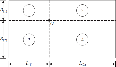
Figure 6.6 Stress below any point of a loaded flexible rectangular area
Expert Solution & Answer
Want to see the full answer?
Check out a sample textbook solution
Students have asked these similar questions
The stresses shown act at a point in a stressed body. The stress magnitudes are Sx = 60 MPa and Sy = 230 MPa, acting in the directions
indicated in the figure. Using the equilibrium equation approach, determine the normal and shear stresses at this point on the inclined
plane shown. Assume B = 49°.
Sy
一
Answer:
Sn =
MPa
Snt =
MPa
The vertical stress at point P due to the
point load Q on the ground surface as
shown in figure is o,. According to
Boussinesq's equation, the vertical
stress at point P, shown in figure will be
z/ 2
P2
r/ 2
P
5. A thin rectangular plate with dimensions 3 cm × 4 cm is acted upon by a stress
distribution which results in the uniform strains
&₁ = 0.0025, &, = 0.0050, &₂ = 0, Y₁ =0.001875, Yx=Y₁ = 0
yz
as shown in the following figure. Determine the change in length of diagonal AB.
▲ y
A
4 cm
B
3 cm
X
Chapter 6 Solutions
Principles of Foundation Engineering (MindTap Course List)
Ch. 6 - A flexible circular area is subjected to a...Ch. 6 - Point loads of magnitude 100, 200, and 400 kN act...Ch. 6 - Refer to Figure P6.3. Determine the vertical...Ch. 6 - Refer to Figure P6.4. A strip load of q = 900...Ch. 6 - Refer to Figure 6.6, which shows a flexible...Ch. 6 - Repeat Problem 6.5 with B1 = 4 ft, B2 = 10 ft, L1...Ch. 6 - Use Eq. (6.14) to determine the stress increase ()...Ch. 6 - Prob. 6.8PCh. 6 - Prob. 6.9PCh. 6 - Prob. 6.10P
Knowledge Booster


Learn more about
Need a deep-dive on the concept behind this application? Look no further. Learn more about this topic, civil-engineering and related others by exploring similar questions and additional content below.Similar questions
- The stresses shown act at a point in a stressed body. The stress magnitudes are Sx = 2200 psi, Sy = 2000 psi, and Sy = 3400 psi, acting in the directions indicated in the figure. Determine the normal and shear stresses at this point on the inclined plane shown. Assume ß = 46°. Sxy S. Answer: Sn i psi Snt = psiarrow_forwardFigure 1a shows a concrete beam supported by twosolid circular columns. Column AB is made from steeland column CD is made from aluminium, see the stressstrain graphs in Figure 1b. The concrete beam issubjected to the load P as shown in Figure 1a.1. Determine the normal stress in column AB andcolumn CD. 2. Determine the relative change in angle of point Cto A in degrees. Given: P= 100KN L1= 3m L2= 2m L3= 1m dAB= 60mm dCD= 60mmarrow_forwardThe stresses shown act at a point in a stressed body. The stress magnitudes are Sx = 55 MPa and Sy = 230 MPa, acting in the directions indicated in the figure. Using the equilibrium equation approach, determine the normal and shear stresses at this point on the inclined plane shown. Assume B = 53°. Sy Sx Answer: MPa Sn = %3D MPа Snt =arrow_forward
- Consider a point in a structural member that is subjected to plane stress. Normal and shear stress magnitudes acting on horizontal and vertical planes at the point are Sx = 28 MPa, Sy = 39 MPa, and Sxy = 36 MPa. . Determine the maximum normal (principal) stress (in MPa) . Express final answer in 7 significant figures.arrow_forwardEXAM QUESTION 2 The state of plane stress at a point is represented by the element shown in the figure. (Assume E=210 GPa, v=0.3). Determine a) the principal stresses and the oriented angle associated with the direction of each principal stress using the transformation equations of plane stress; and b) the absolute maximum shear stress at the point according to this stress matrix. 50 MPa 50 MPa 50 MPaarrow_forwardThe stresses shown act at a point in a stressed body. Normal and shear stress magnitudes acting on horizontal and vertical planes at the point are Sx = 17 MPa, Sy = 29 MPa, and Sxy = 26 MPa. Assume β=tan^−1(b/a)=23.2∘, a = 7, and b = 3. Using the equilibrium equation approach, determine the normal and shear stresses σ (positive if tensile, negative if compressive) and ττ (magnitude only) at this point on the inclined plane shown.arrow_forward
- 50 mm Determine the stress components at point H. And show the stress state for this point on a volume cubic element given below. Cross Section 150 mm 40 mm 0.5 kN 20 mm 3 kN 160 mm 2.5 kNarrow_forwardELABORATE Try solving the following problem: Practice Problem: Refer to Figure 3.8. Determine the vertical stress increaseÃO₂, at point A with the following values: q = 750 lb/ft; x = 8 ft; z = 3 ft. !! Line load = q xarrow_forwardConsider a point in a structural member that is subjected to plane stress. Normal and shear stresses acting on horizontal and vertical planes at the point are shown. If oy= 25 ksi, and the angle 0,= 25.67, determine the magnitude of the maximum in-plane shear stress and the average normal stress values. O O Ţ 8 ksi 45 ksi Tmax= 10.52 ksi and Tmax = 9.21 ksi and Tmax = 12.81 ksi and Tmax = 8.26 ksi and Tmax = 11.60 ksi and = 29.20 ksi avg avg = 45.08 ksi avg = 35.00 ksi avg = 47.36 ksi oavg = 37.92 ksiarrow_forward
- A horizontal load P is applied to an assembly consisting of two inclined bars, as shown in the figure. The cross-sectional area of bar (1) is 1.30 in.2, and the cross-sectional area of bar (2) is 1.75 in.2. The normal stress in either bar may not exceed 24 ksi. Determine the maximum load P that may be applied to this assembly. Assume dimensions of a=14.5 ft, b=9.0 ft, and c=14.5 ft. Find the angle θAB between member (1) and the horizontal direction, and also the angle θBC between member (2) and the horizontal directionarrow_forwardQUESTION 2 For the element shown in Figure q2, the nodal displacements are given as: u₁ (1.5 mm), v₁ (1 mm), u2 (1 mm), v2 (0 mm), u3 (3 mm) and v3 (1.5 mm). The coordinates are given in units of millimeters. Assume plane stress conditions. Let E = 210 GPa, v = 0.25, and t = 8 mm. Determine the principal stresses and the principal angle. Note: No requirement for the stiffness matrix of the element. (40,95) (25,45) 2 (70, 45) FIGURE Q2 UNISA 2022arrow_forward6 mm 80 mm 40 mm r = 20 mm 40 mm a.) Determine the maximum normal stress developed in the bar when it is subjected to a tension of P = 16 kN. The stress concentration factors K can be found from the graphs below. b.) If the bar has an ultimate tensile stress Oult = 275 MPa, and using a factor of safety = 2, determine the maximum tension of P that could be applied to the bar. 3.0 3.2 2.8 2.6 3.0 N- 2.4 Ở avg ht 2r 2.8 2.2 N K 4.0 avg (w – 2r)t K 2.0 3.0 th = 2.0- 2.6 1.8 1.5 1.6 - = 1.2- 2.4 i.i 1.4 2.2 1.2 1.0 2.0 0.1 0.2 0.3 0.4 0.5 0.6 0.7 0.8 0.9 1.0 0.1 0.2 0.3 0.4 0.5 harrow_forward
arrow_back_ios
SEE MORE QUESTIONS
arrow_forward_ios
Recommended textbooks for you
 Principles of Geotechnical Engineering (MindTap C...Civil EngineeringISBN:9781305970939Author:Braja M. Das, Khaled SobhanPublisher:Cengage Learning
Principles of Geotechnical Engineering (MindTap C...
Civil Engineering
ISBN:9781305970939
Author:Braja M. Das, Khaled Sobhan
Publisher:Cengage Learning
Stress Distribution in Soils GATE 2019 Civil | Boussinesq, Westergaard Theory; Author: Gradeup- GATE, ESE, PSUs Exam Preparation;https://www.youtube.com/watch?v=6e7yIx2VxI0;License: Standard YouTube License, CC-BY