
Programmable Logic Controllers
5th Edition
ISBN: 9780073373843
Author: Frank D. Petruzella
Publisher: McGraw-Hill Education
expand_more
expand_more
format_list_bulleted
Textbook Question
Chapter 7, Problem 3P
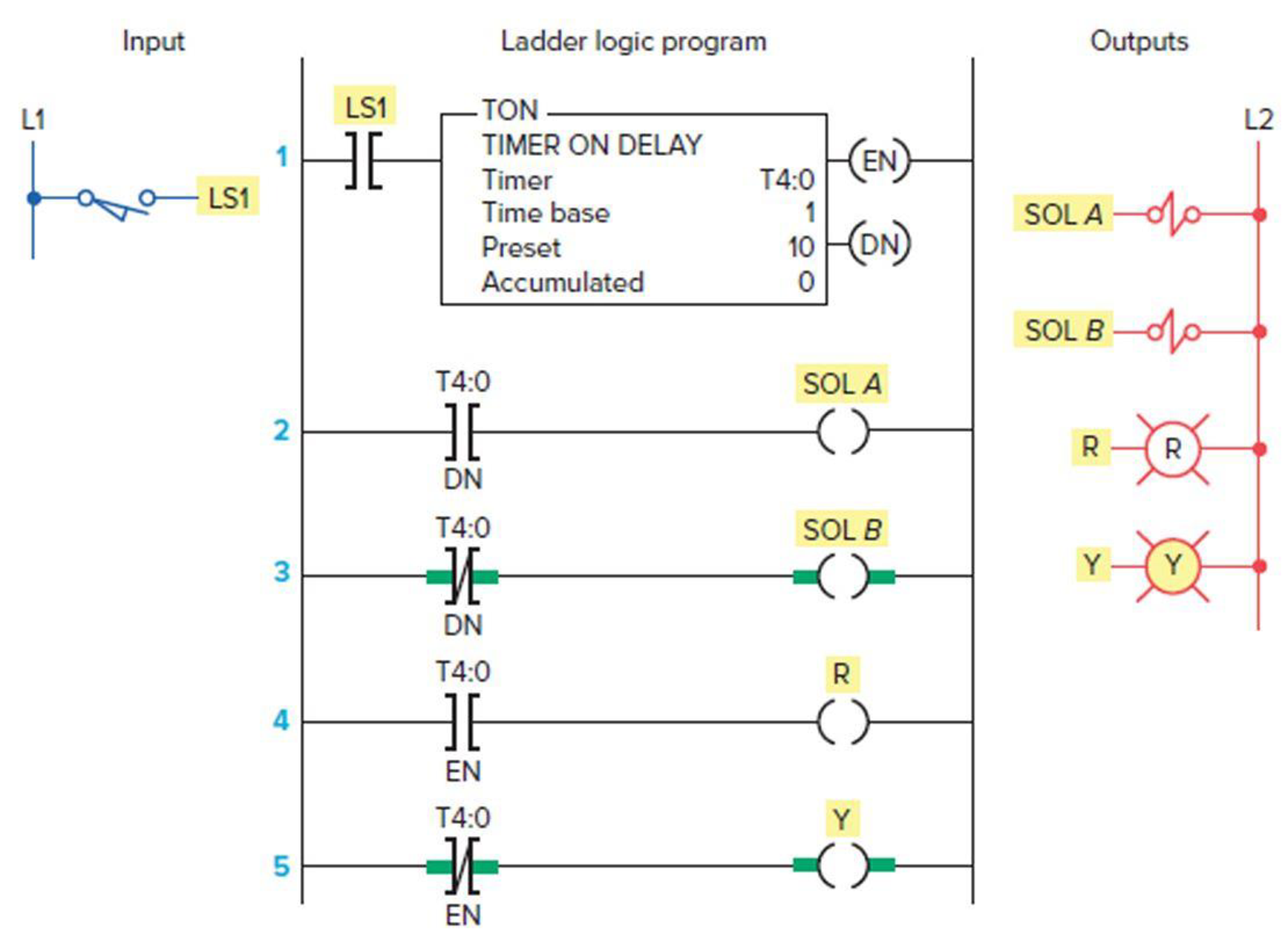
Study the ladder logic program in Figure 7-40 and answer the questions that follow:
- a. What type of timer has been programmed?
- b. What is the length of the time-delay period?
- c. What is the value of the accumulated time when power is first applied?
- d. When does the timer start timing?
- e. When does the timer stop timing and reset itself?
- f. When input LS1 is first closed, which rungs are true and which are false?
- g. When input LS1 is first closed, state the status (on or off) of each output.
- h. When the timer’s accumulated value equals the preset value, which rungs are true and which are false?
- i. When the timer’s accumulated value equals the preset value, state the status (on or off) of each output.
- j. Suppose that rung 1 is true for 5 s and then power is lost. What will the accumulated value of the counter be when power is restored?
Expert Solution & Answer
Want to see the full answer?
Check out a sample textbook solution
Students have asked these similar questions
2. Design a logic circuit with two inputs and 4 outputs, with each of the outputs hooked up to an LED. Only the first LED should light up
when the input values are 00. Only the next LED should light up with the input values are 01. Only the following LED should light up for
10, and only the last LED should light up for input 11. Thus for each input combination, you should have one LED only being lit. This is
called a DECODER circuit, you are decoding 2 bit binary input to one of 4 discrete outputs.
a. Create the truth table (use the standard truth table format).
b. Write a Boolean expression that corresponds to the truth table.
Write python code for a "Count down clock and timer"
Explain how the code works
• Design a sequential circuit with two T Flip Flops, A and B, and two
inputs, E and x. If E=0, the circuit remains in the same state regardless
of the value of x. When E=1 and x=1, the circuit goes through the
state transitions from 00 to 01 to 10 to 11 back to 00, and repeats.
When E=1 and x=0, the circuit goes through the state transition from
00 to 11 to 10 to 01 back to 00, and repeats
Chapter 7 Solutions
Programmable Logic Controllers
Ch. 7 - Prob. 1RQCh. 7 - Prob. 2RQCh. 7 - Prob. 3RQCh. 7 - Prob. 4RQCh. 7 - a. What are the two methods commonly used to...Ch. 7 - Prob. 6RQCh. 7 - Prob. 7RQCh. 7 - Prob. 8RQCh. 7 - For a TOF timer: a. When is the enable bit of a...Ch. 7 - Explain what each of the following quantities...
Ch. 7 - State the method used to reset the accumulated...Ch. 7 - Study the ladder logic program in Figure 7-40 and...Ch. 7 - Study the ladder logic program in Figure 7-42, and...Ch. 7 - Prob. 6PCh. 7 - Prob. 7PCh. 7 - Prob. 8PCh. 7 - Prob. 9PCh. 7 - Prob. 10PCh. 7 - Prob. 11PCh. 7 - Prob. 13PCh. 7 - When the lights are turned off in a building, an...
Additional Engineering Textbook Solutions
Find more solutions based on key concepts
Why might doctors and nutritionists be interested in a device like DietSensor?
Using MIS (10th Edition)
Porter’s competitive forces model: The model is used to provide a general view about the firms, the competitors...
Management Information Systems: Managing The Digital Firm (16th Edition)
(Display three messages) Write a program that displays Welcome to Java, Welcome to Computer Science, and Progra...
Introduction to Java Programming and Data Structures, Comprehensive Version (11th Edition)
Would you select a decoder/driver with active-HIGH or active-LOW outputs to drive a common-cathode 7-segment LE...
Digital Fundamentals (11th Edition)
What are the design issues for character string types?
Concepts Of Programming Languages
Computers can do many different jobs because they can be_____.
Starting Out with C++: Early Objects (9th Edition)
Knowledge Booster

Similar questions
- 1. Design a logic circuit that has 3 inputs A, B, and Cand one output F. The output of the circuit is to be F = 1if the number of ones in input variables (ABC) is even, otherwise F=0. Construct the truth table. 2. Fnd the minterm expansion for the combinational circuit represented by the following truth table: АВСЕ 0000 0011 0100 0111 1001 1011 1100 1111 Use the editor to format your answerarrow_forward6. Predict the output from each gate for the input variables shown: C A D B E Find out the values of C, D, E, F and G (show your calculation how you are getting the numbers) Input: A = 0 and B = 0 Find C, D. E, F, and G Each answer will be either 0 or 1arrow_forwardDevelop the ladder logic diagram to fill the tank. 1. Filling the water tank up to 80%. When the tank is filled, turn ON the heater to raise the temperature up to 70-degree C.2. when this temperature is reached, turn OFF the heater & open the outlet valve.3. When the level in the tank falls below 10%, closes the output valve and start filling the tank again.4. A digital counter is used to monitor the number of times the tank is emptied (reaches 10%). Once the counter reaches to 8 times, the system is stopped.arrow_forward
- 1. Which of following lists all possible input combinations for a gate, and the corresponding output? O A. truth table B. Boolean expression OC. logic diagram D. circuit O E. S-R latcharrow_forwardPlease design a circuit that has a red led and a blue led and simulates a police light (i.e: The red led turns on and off periodically and it gives light when the blue one doesn't, then it turns off when the blue one turns on.)arrow_forward2. Design a logic circuit that controls an elevator door in a three-story building. The circuit has four inputs. M is a logic signal that indicates when an elevator is moving (M=1) or stopped (M=0). F1, F2 and F3 are floor indicator signals that are normally LOW, and they go HIGH only when the elevator is positioned at the level of that particular floor. For example, when the elevator is lined up level with the second floor, F2=1 and F1=F3=0. The circuit output is the OPEN signal which is normally LOW and is to go HIGH when the elevator door is to be opened.arrow_forward
- Develop a python program to create clock-controlled latches. Your program should have the following sequence to test the circuit operation, as follows: describe how you were able to make it and how come this code was successful. Thanks a million!arrow_forwardQ1/ Estimate the Truth Table of the logic circuit shown below and use it to draw the timing diagram of the output signal X and Y in proper relation to the inputs A :: Y сеarrow_forward1. Write Boolean equations for the circuit shown below. They do not need to be optimized. A B D X Y Zarrow_forward
arrow_back_ios
SEE MORE QUESTIONS
arrow_forward_ios
Recommended textbooks for you
 Database System ConceptsComputer ScienceISBN:9780078022159Author:Abraham Silberschatz Professor, Henry F. Korth, S. SudarshanPublisher:McGraw-Hill Education
 Starting Out with Python (4th Edition)Computer ScienceISBN:9780134444321Author:Tony GaddisPublisher:PEARSON
 Digital Fundamentals (11th Edition)Computer ScienceISBN:9780132737968Author:Thomas L. FloydPublisher:PEARSON
 C How to Program (8th Edition)Computer ScienceISBN:9780133976892Author:Paul J. Deitel, Harvey DeitelPublisher:PEARSON
 Database Systems: Design, Implementation, & Manag...Computer ScienceISBN:9781337627900Author:Carlos Coronel, Steven MorrisPublisher:Cengage Learning
 Programmable Logic ControllersComputer ScienceISBN:9780073373843Author:Frank D. PetruzellaPublisher:McGraw-Hill Education
Database System Concepts
Computer Science
ISBN:9780078022159
Author:Abraham Silberschatz Professor, Henry F. Korth, S. Sudarshan
Publisher:McGraw-Hill Education
Starting Out with Python (4th Edition)
Computer Science
ISBN:9780134444321
Author:Tony Gaddis
Publisher:PEARSON
Digital Fundamentals (11th Edition)
Computer Science
ISBN:9780132737968
Author:Thomas L. Floyd
Publisher:PEARSON
C How to Program (8th Edition)
Computer Science
ISBN:9780133976892
Author:Paul J. Deitel, Harvey Deitel
Publisher:PEARSON
Database Systems: Design, Implementation, & Manag...
Computer Science
ISBN:9781337627900
Author:Carlos Coronel, Steven Morris
Publisher:Cengage Learning
Programmable Logic Controllers
Computer Science
ISBN:9780073373843
Author:Frank D. Petruzella
Publisher:McGraw-Hill Education