
ENGINEERING CIRCUIT...(LL)>CUSTOM PKG.<
9th Edition
ISBN: 9781260540666
Author: Hayt
Publisher: MCG CUSTOM
expand_more
expand_more
format_list_bulleted
Videos
Textbook Question
Chapter 4.3, Problem 8P
Determine i1 in the circuit of Fig. 4.24 if the controlling quantity A is equal to (a) 2i2; (b) 2vx.
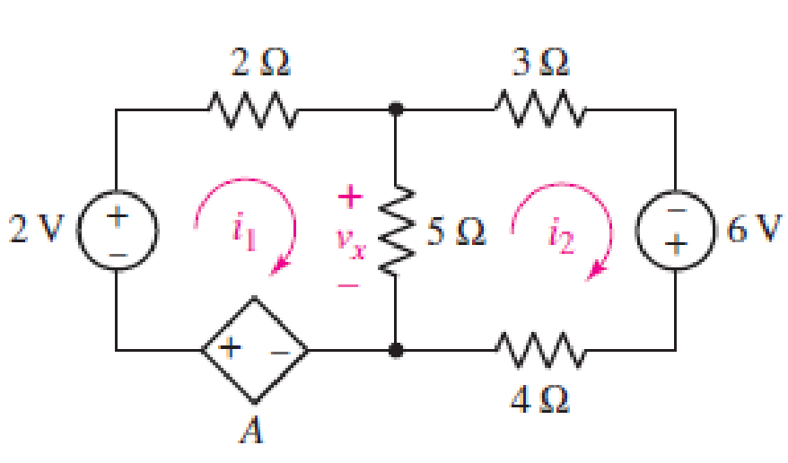
FIGURE 4.24
Expert Solution & Answer
Want to see the full answer?
Check out a sample textbook solution
Students have asked these similar questions
Please answer in typing format please ASAP for the
Please in typing format please ASAP
I need it urgently
provide implicit general solution, show all steps please
Consider the circuit in Figure 4.
a) Find the Thevenin equivalent of the network connected to the capacitor C1.
b) Find the mathematical equations for the transient behavior of voltage vc(t) and the current ic(t)
following the closing of the switch.
c) Determine the value of voltage vc at t = 100 ms.
%3D
TC LOSE = 0
R1
TK
V1
15V
6K
R2
LIK
R3
C1
R4
0.
3K
Chapter 4 Solutions
ENGINEERING CIRCUIT...(LL)>CUSTOM PKG.<
Ch. 4.1 - For the circuit of Fig. 4.3, determine the nodal...Ch. 4.1 - For the circuit of Fig. 4.5, compute the voltage...Ch. 4.1 - For the circuit of Fig. 4.8, determine the nodal...Ch. 4.2 - For the circuit of Fig. 4.11, compute the voltage...Ch. 4.3 - Determine i1 and i2 in the circuit in Fig. 4.19....Ch. 4.3 - Determine i1 and i2 in the circuit of Fig 4.21....Ch. 4.3 - Determine i1 in the circuit of Fig. 4.24 if the...Ch. 4.4 - Determine the current i1 in the circuit of Fig....Ch. 4.4 - Determine v3 in the circuit of Fig. 4.28. FIGURE...Ch. 4 - Solve the following systems of equations: (a) 2v2 ...
Ch. 4 - (a) Solve the following system of equations:...Ch. 4 - (a) Solve the following system of equations:...Ch. 4 - Correct (and verify by running) the following...Ch. 4 - In the circuit of Fig. 4.35, determine the current...Ch. 4 - Calculate the power dissipated in the 1 resistor...Ch. 4 - For the circuit in Fig. 4.37, determine the value...Ch. 4 - With the assistance of nodal analysis, determine...Ch. 4 - Prob. 9ECh. 4 - For the circuit of Fig. 4.40, determine the value...Ch. 4 - Use nodal analysis to find vP in the circuit shown...Ch. 4 - Prob. 12ECh. 4 - Prob. 13ECh. 4 - Determine a numerical value for each nodal voltage...Ch. 4 - Prob. 15ECh. 4 - Using nodal analysis as appropriate, determine the...Ch. 4 - Prob. 17ECh. 4 - Determine the nodal voltages as labeled in Fig....Ch. 4 - Prob. 19ECh. 4 - Prob. 20ECh. 4 - Employing supernode/nodal analysis techniques as...Ch. 4 - Prob. 22ECh. 4 - Prob. 23ECh. 4 - Prob. 24ECh. 4 - Repeat Exercise 23 for the case where the 12 V...Ch. 4 - Prob. 26ECh. 4 - Prob. 27ECh. 4 - Determine the value of k that will result in vx...Ch. 4 - Prob. 29ECh. 4 - Prob. 30ECh. 4 - Prob. 31ECh. 4 - Determine the currents flowing out of the positive...Ch. 4 - Obtain numerical values for the two mesh currents...Ch. 4 - Use mesh analysis as appropriate to determine the...Ch. 4 - Prob. 35ECh. 4 - Prob. 36ECh. 4 - Find the unknown voltage vx in the circuit in Fig....Ch. 4 - Prob. 38ECh. 4 - Prob. 39ECh. 4 - Determine the power dissipated in the 4 resistor...Ch. 4 - (a) Employ mesh analysis to determine the power...Ch. 4 - Define three clockwise mesh currents for the...Ch. 4 - Prob. 43ECh. 4 - Prob. 44ECh. 4 - Prob. 45ECh. 4 - Prob. 46ECh. 4 - Prob. 47ECh. 4 - Prob. 48ECh. 4 - Prob. 49ECh. 4 - Prob. 50ECh. 4 - Prob. 51ECh. 4 - Prob. 52ECh. 4 - For the circuit represented schematically in Fig....Ch. 4 - The circuit of Fig. 4.80 is modified such that the...Ch. 4 - The circuit of Fig. 4.81 contains three sources....Ch. 4 - Solve for the voltage vx as labeled in the circuit...Ch. 4 - Consider the five-source circuit of Fig. 4.83....Ch. 4 - Replace the dependent voltage source in the...Ch. 4 - After studying the circuit of Fig. 4.84, determine...Ch. 4 - Prob. 60ECh. 4 - Employ LTspice (or similar CAD tool) to verify the...Ch. 4 - Employ LTspice (or similar CAD tool) to verify the...Ch. 4 - Employ LTspice (or similar CAD tool) to verify the...Ch. 4 - Verify numerical values for each nodal voltage in...Ch. 4 - Prob. 65ECh. 4 - Prob. 66ECh. 4 - Prob. 67ECh. 4 - Prob. 68ECh. 4 - Prob. 69ECh. 4 - (a) Under what circumstances does the presence of...Ch. 4 - Referring to Fig. 4.88, (a) determine whether...Ch. 4 - Consider the LED circuit containing a red, green,...Ch. 4 - The LED circuit in Fig. 4.89 is used to mix colors...Ch. 4 - A light-sensing circuit is in Fig. 4.90, including...Ch. 4 - Use SPICE to analyze the circuit in Exercise 74 by...
Knowledge Booster


Learn more about
Need a deep-dive on the concept behind this application? Look no further. Learn more about this topic, electrical-engineering and related others by exploring similar questions and additional content below.Similar questions
- Q2. For the diode logic circuits shown in Fig. 4.2, find the output voltage and the diode currents for the particular input values shown. Model a conducting diode as a constant voltage drop of 0.7 V. +5 V OVO IDI DI ID2 K K D₂ (a) +5 V • 10 ΚΩ o Vo +5 Vo OVO- Fig. 4.2 IDI DI ID2 D₂ K₂ (b) H 10 ΚΩ - Voarrow_forwardCan you provide me the detail answer about alexander electric circuits problem 4.48arrow_forwardQ4/ A) For the circuit shown below, calculate the current i, the conductance G, and the power P. 30 V (+ 5 k2arrow_forward
- 4. Please give handwritten answerarrow_forwardNeeds Complete solution don't use chat gpt or ai i definitely upvote you be careful Downvote for ai or chat gpt answer.arrow_forwardQ4(b)) Figure 1(b) shows the schematic diagram of a potentiometer for the measurement of displacement. i) Detemine the relationship between output voltage V, and the input voltage V, , as a function of x and the ratio of total displacement if the load resistance is R. Solve for the output voltage, V at 0.75 reading of the potentiometer for the value of the resistance ratio Rp/R= 2%. Rp(1-x) Rp Rp(0arrow_forward
- Please calculate all parts a,b,c,darrow_forwardConsider the circuit in Figure 4. a) Find the Thevenin equivalent of the network connected to the capacitor C1. b) Find the mathematical equations for the transient behavior of voltage ve(t) and the current ic(t) following the closing of the switch. c) Determine the value of voltage ve at t=100 ms. TCLOSE = 0 R1 1. 21 5k 30 V VI 3k R2 2k R3 C1 33UF R4 1k 0.arrow_forwardQ4: A 6V battery delivers 10MA to three resistors in parallel, R1 1kN, R2= 2kN, R3= Rx. Calculate : a) Current in Rx, that is Ix. [Ans: 1mA] b) Power dissipated by Rx and R1. c) Resistance ratio "*/R1• [Ans: 6mw, 36mw] [Ans: /1] 14 d) Current ratio [Ans: /1]arrow_forward
- 4.4.2 Use of the Zener as a Shunt Regulator The 6.8-V zener diode in the circuit of Fig. 4.19(a) is specified to have V, 6.8 V at I, = 5 mA. r = 20 2, and Ix = 0.2 mA. The supply voltage V* is nominally 10 V but can vary by t1 v. AV* (10 =1 V) R 0.5 kn Vzo Vo RL 6.8-V, Vo zener (b) (a) Figure 4.19 (a) Circuit for Example 4.7. (b) The circuit with the zener diode replaced with its equivalent circuit 62 model.arrow_forwardHelp pls. I will upvote, Thankyou :)arrow_forward(a) Simplify the circuit shown in Figure Q4 (a) into single voltage source by applying source transformation and determine the current, io. 3 A 6 A 20 V Figure Q4 (a)arrow_forward
arrow_back_ios
SEE MORE QUESTIONS
arrow_forward_ios
Recommended textbooks for you
 Introductory Circuit Analysis (13th Edition)Electrical EngineeringISBN:9780133923605Author:Robert L. BoylestadPublisher:PEARSON
 Delmar's Standard Textbook Of ElectricityElectrical EngineeringISBN:9781337900348Author:Stephen L. HermanPublisher:Cengage Learning
 Programmable Logic ControllersElectrical EngineeringISBN:9780073373843Author:Frank D. PetruzellaPublisher:McGraw-Hill Education
 Fundamentals of Electric CircuitsElectrical EngineeringISBN:9780078028229Author:Charles K Alexander, Matthew SadikuPublisher:McGraw-Hill Education
 Electric Circuits. (11th Edition)Electrical EngineeringISBN:9780134746968Author:James W. Nilsson, Susan RiedelPublisher:PEARSON
 Engineering ElectromagneticsElectrical EngineeringISBN:9780078028151Author:Hayt, William H. (william Hart), Jr, BUCK, John A.Publisher:Mcgraw-hill Education,
Introductory Circuit Analysis (13th Edition)
Electrical Engineering
ISBN:9780133923605
Author:Robert L. Boylestad
Publisher:PEARSON
Delmar's Standard Textbook Of Electricity
Electrical Engineering
ISBN:9781337900348
Author:Stephen L. Herman
Publisher:Cengage Learning
Programmable Logic Controllers
Electrical Engineering
ISBN:9780073373843
Author:Frank D. Petruzella
Publisher:McGraw-Hill Education
Fundamentals of Electric Circuits
Electrical Engineering
ISBN:9780078028229
Author:Charles K Alexander, Matthew Sadiku
Publisher:McGraw-Hill Education
Electric Circuits. (11th Edition)
Electrical Engineering
ISBN:9780134746968
Author:James W. Nilsson, Susan Riedel
Publisher:PEARSON
Engineering Electromagnetics
Electrical Engineering
ISBN:9780078028151
Author:Hayt, William H. (william Hart), Jr, BUCK, John A.
Publisher:Mcgraw-hill Education,
Mesh Current Problems in Circuit Analysis - Electrical Circuits Crash Course - Beginners Electronics; Author: Math and Science;https://www.youtube.com/watch?v=DYg8B-ElK0s;License: Standard Youtube License