
Concept explainers
Videos
The LED circuit in Fig. 4.89 is used to mix colors to achieve any desired color in the RGB color palette. Use LTspice and the circuit model representing LEDs as voltage sources to see how changing the resistance R1 from 100 to 1 kΩ affects the color, with the other resistors fixed at R2 = R3 = 100 Ω. You can do this using a parameter sweep statement by defining a variable such as {rvariable} (including the curly brackets) in the value for R1. Then include a SPICE directive such as .step param rvariable 100 1k 20 to step the variable from 100 to 1000 in steps of 20. (a) Plot the current of all three LEDs as a function of R1 and explain the result. (b) Find an RGB color chart and describe how the color changes with R1, increasing from 100 to 1 kΩ. (c) Find a value of R1 that could be used to achieve a khaki color approximating RGB hex code C2BD23, RGB (194,189,35).
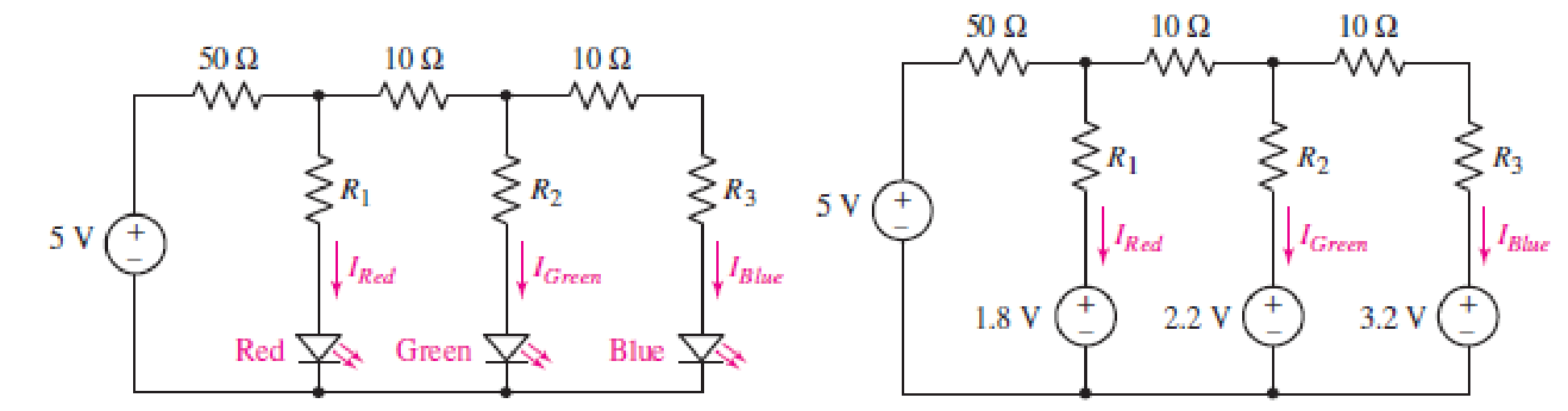
FIGURE 4.89
Want to see the full answer?
Check out a sample textbook solution
Chapter 4 Solutions
ENGINEERING CIRCUIT...(LL)>CUSTOM PKG.<


- When comparing the generation of analogue output from a digital system using PWM and DAC which of the following statements is NOT true? PWM generally has limited resolution compared with DAC PWM generally has better noise performance than a DAC PWM is a lower cost and simpler method of generating analogue output than using a DAC. DACS tend to have a higher system cost than the equivalent system implemented using PWMarrow_forward(3) 4. a. For the cicuit to the the right show that:. H(@) = (-C,R₂) jo (1+ joRC) (1+ jwR₂C₂) R₁ G₁ Ⓒut) R₂ C₂ % (4)arrow_forwardConsider Two same size PV Modules which are connected in Parallel. The specification of each module is given as: Number of cells = 36, Area of each cell is 12 cm x 12 cm. (Assume the necessary data) Choose from the following the correct statement. a. The output voltage of this panel is 18 V, the output power is 155W b. The output voltage is this panel 18V, the output power is 75W c. The output voltage is this panel 36 V, the output power is 155W d. The output voltage is this panel 36 V, the output power is 75Warrow_forward
- Pls help on this question. Please show all the work meaning that pls show how you got the values which you will put in the table. Pls pls pls show all work. Write neatly and explain which value you are finding.arrow_forwardThe LED in the circuit requires 200mA to emit sufficient level of light. Determine the base resistance needed to turn on the LED when the input voltage is increased to 5V and Rc = 220 ohms. Please hand written solutionarrow_forwardSuppose you have a voltage signal x and you want to produce another voltage signal y such that y = [xInx dt. %| Design a circuit that will do the operation for you and generate y. Hint: In(a) + In(b) = In(ab) and en (x) = x. How did we produce x2 ?arrow_forward
- i need it handwriting and how to simplfiy the equation plsarrow_forward1. ) Minimize the following DFA using a. Huffman algorithm using Distinct table. For each step draw a separate Distinct table. 0, 1 1 q1 q2 q4 qo 93 1 95 1. 1.arrow_forwardBy the aid of constant-voltage model, sketch the input/output characteristics of the circuit depicted in Figurex. 叫竹 Vin 1 Kr D4 # D3 4K Voutarrow_forward
- mpt3D1966098&cmid%3D11648 My Courses This course c. 11= 10 A, 12 = 5 A, V=50 V O d. 11 5 A, 12 = 2.5 A, V=25 V Question 5 For this circuit Is and V2 = Not yet R1 R2 R3 answered Marked out of 6.00 P Flag question V2 Is Vs R4 12 V Select one: O a. Is = 1 A, V2= 4 V O b. Is = 2 A, V2= 2V Oc. Is = 2 A, V2= 4 V O d. Is = 1 A, V2= 2 V Question 6 Use current division to find the currenti 120 flowing through the 120 resist Not yet answered Marked out of 28 7.00 +arrow_forwardSolve for: a. Id (atleast 4 decimal place) b. Vgs c. Vd (Atleast 3 decimal value) d. Vs a. Id-Blank 1 mA b. Vgs-Blank 2V c. Vd-Blank 3V d. Vs-Blank 4 V Blank 1 Add your answer Blank 2 Add your answer Blank 3 Add your answer Blank 4 Add your answer c). 1 MQ 1.5V. 12 V 1.210 Ing Vaso oss = 12 mA V₂ =-4Varrow_forwardWhen ##= 9 find what is asked in a and b. Thank you.arrow_forward
 Introductory Circuit Analysis (13th Edition)Electrical EngineeringISBN:9780133923605Author:Robert L. BoylestadPublisher:PEARSON
 Delmar's Standard Textbook Of ElectricityElectrical EngineeringISBN:9781337900348Author:Stephen L. HermanPublisher:Cengage Learning
 Programmable Logic ControllersElectrical EngineeringISBN:9780073373843Author:Frank D. PetruzellaPublisher:McGraw-Hill Education
 Fundamentals of Electric CircuitsElectrical EngineeringISBN:9780078028229Author:Charles K Alexander, Matthew SadikuPublisher:McGraw-Hill Education
 Electric Circuits. (11th Edition)Electrical EngineeringISBN:9780134746968Author:James W. Nilsson, Susan RiedelPublisher:PEARSON
 Engineering ElectromagneticsElectrical EngineeringISBN:9780078028151Author:Hayt, William H. (william Hart), Jr, BUCK, John A.Publisher:Mcgraw-hill Education,