
ENGINEERING CIRCUIT...(LL)>CUSTOM PKG.<
9th Edition
ISBN: 9781260540666
Author: Hayt
Publisher: MCG CUSTOM
expand_more
expand_more
format_list_bulleted
Concept explainers
Videos
Textbook Question
Chapter 4, Problem 28E
Determine the value of k that will result in vx being equal to zero in the circuit of Fig. 4.56.
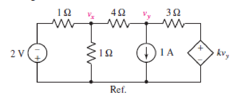
FIGURE 4.56
Expert Solution & Answer
Want to see the full answer?
Check out a sample textbook solution
Students have asked these similar questions
Q5 Draw the output voltage waveform for each circuit in Fig. 4.30 with respect to
the input. Show voltage levels.
+I V
+1 V
0-
-I V
+2 V
Vutmery = 18 V
-2 V
(a)
(b)
Using Fig. 4.78, design a problem to help other students better understand superposition. Note, the letter k is a gain you can specify to make the problem easier to solve but must not be zero
Obtain numerical values for the two mesh currents ij and iz in the circuit
shown in Fig. 4.61.
32
5 V
iz
12 V
14 2
Chapter 4 Solutions
ENGINEERING CIRCUIT...(LL)>CUSTOM PKG.<
Ch. 4.1 - For the circuit of Fig. 4.3, determine the nodal...Ch. 4.1 - For the circuit of Fig. 4.5, compute the voltage...Ch. 4.1 - For the circuit of Fig. 4.8, determine the nodal...Ch. 4.2 - For the circuit of Fig. 4.11, compute the voltage...Ch. 4.3 - Determine i1 and i2 in the circuit in Fig. 4.19....Ch. 4.3 - Determine i1 and i2 in the circuit of Fig 4.21....Ch. 4.3 - Determine i1 in the circuit of Fig. 4.24 if the...Ch. 4.4 - Determine the current i1 in the circuit of Fig....Ch. 4.4 - Determine v3 in the circuit of Fig. 4.28. FIGURE...Ch. 4 - Solve the following systems of equations: (a) 2v2 ...
Ch. 4 - (a) Solve the following system of equations:...Ch. 4 - (a) Solve the following system of equations:...Ch. 4 - Correct (and verify by running) the following...Ch. 4 - In the circuit of Fig. 4.35, determine the current...Ch. 4 - Calculate the power dissipated in the 1 resistor...Ch. 4 - For the circuit in Fig. 4.37, determine the value...Ch. 4 - With the assistance of nodal analysis, determine...Ch. 4 - Prob. 9ECh. 4 - For the circuit of Fig. 4.40, determine the value...Ch. 4 - Use nodal analysis to find vP in the circuit shown...Ch. 4 - Prob. 12ECh. 4 - Prob. 13ECh. 4 - Determine a numerical value for each nodal voltage...Ch. 4 - Prob. 15ECh. 4 - Using nodal analysis as appropriate, determine the...Ch. 4 - Prob. 17ECh. 4 - Determine the nodal voltages as labeled in Fig....Ch. 4 - Prob. 19ECh. 4 - Prob. 20ECh. 4 - Employing supernode/nodal analysis techniques as...Ch. 4 - Prob. 22ECh. 4 - Prob. 23ECh. 4 - Prob. 24ECh. 4 - Repeat Exercise 23 for the case where the 12 V...Ch. 4 - Prob. 26ECh. 4 - Prob. 27ECh. 4 - Determine the value of k that will result in vx...Ch. 4 - Prob. 29ECh. 4 - Prob. 30ECh. 4 - Prob. 31ECh. 4 - Determine the currents flowing out of the positive...Ch. 4 - Obtain numerical values for the two mesh currents...Ch. 4 - Use mesh analysis as appropriate to determine the...Ch. 4 - Prob. 35ECh. 4 - Prob. 36ECh. 4 - Find the unknown voltage vx in the circuit in Fig....Ch. 4 - Prob. 38ECh. 4 - Prob. 39ECh. 4 - Determine the power dissipated in the 4 resistor...Ch. 4 - (a) Employ mesh analysis to determine the power...Ch. 4 - Define three clockwise mesh currents for the...Ch. 4 - Prob. 43ECh. 4 - Prob. 44ECh. 4 - Prob. 45ECh. 4 - Prob. 46ECh. 4 - Prob. 47ECh. 4 - Prob. 48ECh. 4 - Prob. 49ECh. 4 - Prob. 50ECh. 4 - Prob. 51ECh. 4 - Prob. 52ECh. 4 - For the circuit represented schematically in Fig....Ch. 4 - The circuit of Fig. 4.80 is modified such that the...Ch. 4 - The circuit of Fig. 4.81 contains three sources....Ch. 4 - Solve for the voltage vx as labeled in the circuit...Ch. 4 - Consider the five-source circuit of Fig. 4.83....Ch. 4 - Replace the dependent voltage source in the...Ch. 4 - After studying the circuit of Fig. 4.84, determine...Ch. 4 - Prob. 60ECh. 4 - Employ LTspice (or similar CAD tool) to verify the...Ch. 4 - Employ LTspice (or similar CAD tool) to verify the...Ch. 4 - Employ LTspice (or similar CAD tool) to verify the...Ch. 4 - Verify numerical values for each nodal voltage in...Ch. 4 - Prob. 65ECh. 4 - Prob. 66ECh. 4 - Prob. 67ECh. 4 - Prob. 68ECh. 4 - Prob. 69ECh. 4 - (a) Under what circumstances does the presence of...Ch. 4 - Referring to Fig. 4.88, (a) determine whether...Ch. 4 - Consider the LED circuit containing a red, green,...Ch. 4 - The LED circuit in Fig. 4.89 is used to mix colors...Ch. 4 - A light-sensing circuit is in Fig. 4.90, including...Ch. 4 - Use SPICE to analyze the circuit in Exercise 74 by...
Knowledge Booster


Learn more about
Need a deep-dive on the concept behind this application? Look no further. Learn more about this topic, electrical-engineering and related others by exploring similar questions and additional content below.Similar questions
- Q5 Draw the output voltage waveform for each circuit in Fig. 4.30 with respect the input. Show voltage levels. +1 V +1 V 0- -I V +2 V Vunmuy = 18 V Vrtmna = 110 V %3D -2 V (a) (b)arrow_forwardAn attenuator is an interface circuit that reduces the voltage level without changing the output resistance. (a) By specifying R, and R, of the interface circuit in Fig. 4.150, design an attenuator that will meet the following requirements: V. 0.125, Vg Rea = RTh = Rg = 100 N (b) Using the interface designed in part (a), calculate the current through a load of R1 = 50 N when V = 12 V. R, Rp RL Load Attenuator Reg In part (a) determine the values of Rs and RP. ww wwwarrow_forwardFind the Norton equivalent circuit of the circuit in Fig. 4.45 at terminals a-h. 60 10 A 20 Figure 4.45 ww wwarrow_forward
- Obtain the value of the rated current i10 in the circuit of figure 4.80arrow_forwardQ4(a) For the circuit shown in Figure Q4 (a), find the Thevenin equivalent with respect to terminals "a-b". 2 A 20 Ω ww 120 V 40 2 12 2 Figure Q4 (a) wwarrow_forward4.19 Use superposition to solve for v, in the circuit of Fig. 4.87. Vx ) 6 A 4 A (4) 4ix Figure 4.87arrow_forward
- Find the Norton equivalent circuit for the circuit in Fig. 4.42, at terminals a-b.arrow_forwardGiven that I =6 amps when V, = 160 volts and I, = -10 amps and I= 5 amp when V, = 200 volts and I, = 0, use superposition and linearity to determine the value of I when V = 120 volts and I, = 5 amps. 4.9 %3D %3D ww Ve Is (4) S Figure 4.77 For Prob. 4.9.arrow_forward(a) Use the source transformation technique to solve V, in the circuit of Figure Q4(a). 30 2 40 2 10 2 30 Ω 15 V 20 V Figure Q4(a) wwarrow_forward
- 4.1 Calculate the current i, in the circuit of Fig. 4.69. What value of input voltage is necessary to make i, equal to 5 amps? 5Ω 2592 ww ww 30 V Figure 4.69 For Prob. 4.1. 40 Ω o 15 Ω please answer in typingarrow_forward* Determine the value of RL that will draw the maximum power from the rest of the circuit in Fig. 4.5.4. Calculate the maximum power 4 2 + Vx 10 9 V + RL 3v% Figure 4.5.4 For Practice Prob. above. Answer: 4.2222, 2.901 W.arrow_forwardc) Analyse the steady-state voltage vo(t) of the circuit in Figure Q4(b) if the input voltage is given by: v;(t) = 7.5 cos(2t - 122°) +2.2 cos(6t – 102°) +1.3 cos(10t – 97°) + 0.91 cos(14t – 95°) + ... V Show your answer for the first four terms of the output voltage, Vo(t).arrow_forward
arrow_back_ios
SEE MORE QUESTIONS
arrow_forward_ios
Recommended textbooks for you
 Introductory Circuit Analysis (13th Edition)Electrical EngineeringISBN:9780133923605Author:Robert L. BoylestadPublisher:PEARSON
 Delmar's Standard Textbook Of ElectricityElectrical EngineeringISBN:9781337900348Author:Stephen L. HermanPublisher:Cengage Learning
 Programmable Logic ControllersElectrical EngineeringISBN:9780073373843Author:Frank D. PetruzellaPublisher:McGraw-Hill Education
 Fundamentals of Electric CircuitsElectrical EngineeringISBN:9780078028229Author:Charles K Alexander, Matthew SadikuPublisher:McGraw-Hill Education
 Electric Circuits. (11th Edition)Electrical EngineeringISBN:9780134746968Author:James W. Nilsson, Susan RiedelPublisher:PEARSON
 Engineering ElectromagneticsElectrical EngineeringISBN:9780078028151Author:Hayt, William H. (william Hart), Jr, BUCK, John A.Publisher:Mcgraw-hill Education,
Introductory Circuit Analysis (13th Edition)
Electrical Engineering
ISBN:9780133923605
Author:Robert L. Boylestad
Publisher:PEARSON
Delmar's Standard Textbook Of Electricity
Electrical Engineering
ISBN:9781337900348
Author:Stephen L. Herman
Publisher:Cengage Learning
Programmable Logic Controllers
Electrical Engineering
ISBN:9780073373843
Author:Frank D. Petruzella
Publisher:McGraw-Hill Education
Fundamentals of Electric Circuits
Electrical Engineering
ISBN:9780078028229
Author:Charles K Alexander, Matthew Sadiku
Publisher:McGraw-Hill Education
Electric Circuits. (11th Edition)
Electrical Engineering
ISBN:9780134746968
Author:James W. Nilsson, Susan Riedel
Publisher:PEARSON
Engineering Electromagnetics
Electrical Engineering
ISBN:9780078028151
Author:Hayt, William H. (william Hart), Jr, BUCK, John A.
Publisher:Mcgraw-hill Education,
Norton's Theorem and Thevenin's Theorem - Electrical Circuit Analysis; Author: The Organic Chemistry Tutor;https://www.youtube.com/watch?v=-kkvqr1wSwA;License: Standard Youtube License