
Videos
(a) Employ mesh analysis to determine the power dissipated by the 1 Ω resistor in the circuit represented schematically by Fig. 4.68. (b) Check your answer using nodal analysis.
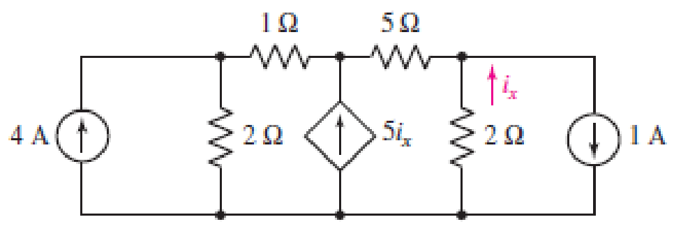
■ FIGURE 4.68
(a)
Employ mess analysis to find the power dissipated by the
Answer to Problem 41E
The power dissipated by the
Explanation of Solution
Calculation:
The circuit diagram is redrawn as shown in Figure 1,
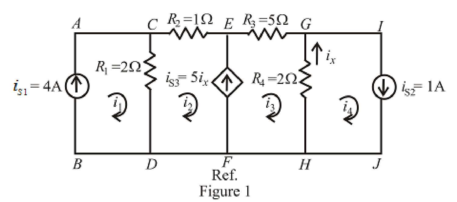
Refer to the redrawn Figure 1,
Apply KVL in the mesh
Here,
The expression for the current flowing in the branch
Here,
The expression for the current flowing in the branch
Here,
The expression for the power dissipated by the
Here,
Refer to the redrawn Figure 1,
Substitute
Rearrange equation (5),
Substitute
Substitute
Substitute
Rearrange the above equation for
Substitute
Rearrange for
Substitute
Substitute
Conclusion:
Thus, the power dissipated by the
(b)
Check the answer by nodal analysis.
Explanation of Solution
Formula used:
Refer to the redrawn Figure 1,
Apply KCL at node
Here,
Apply KCL at node
Here,
The expression for the current flowing in the branch
Apply KCL at node
Here,
The expression for the power dissipated by the
Here,
Calculation:
Refer to the redrawn Figure 1,
Substitute
Substitute
Substitute
Substitute
Substitute
Rearrange equation (13), (14) and (15),
The equations so formed can be written in matrix form as,
Therefore, by Cramer’s rule,
The determinant of the coefficient matrix is as follows,
The 1st determinant is as follows,
The 2nd determinant is as follows,
The 3rd determinant is as follows,
Simplify for
Simplify for
Simplify for
Substitute
So, the power dissipated by the
Conclusion:
Thus, the answer is checked by using nodal analysis.
Want to see more full solutions like this?
Chapter 4 Solutions
ENGINEERING CIRCUIT...(LL)>CUSTOM PKG.<


- a) Apply nodal analysis to solve for Vx in the circuit of figure Ba. Copyright © The McGraw-Hill Companies, Inc. Permission required for reproduction or display 2 A (4) 10 Ω V 20 Ω 0.2Vx Figure Ba b) A battery has a short-circuit current of 20-A and an open-circuit voltage of 12-V. If the battery is connected to an electric bulb of resistance 2-0, calculate the power dissipated by the bulb. +arrow_forward6. a) Use the mesh-current method to write a complete set of equations that could be used to solve this circuit. Do not simplify the circuit. Do not attempt to solve or simplify your equations. Define all variables. b) Compare the number of equations required using the node-voltage method and the mesh current method, for this circuit. Which method requires fewer equations? 32[0] 24[Q] 28[Q] 11[O]ix 31[Q) 30[0] | 2[V] 33[Q] i 34[Q] 35[0] 3[A] 38[0] 29[0] 10[O]i 4[V] Vr 36[2] 37[0] 6[A] 5[V] 25[0]arrow_forwardQ4 (a) Figure Q4(a) shows a two-port network circuit. (i) (ii) Calculate the admittance parameters of the circuit. Based on the answers in part Q4(a)(i), deduce the equivalent circuit for the circuit in Figure Q4(a). V₁ ö 1092 W 12.5Ω W m 552 W 552 Figure Q4(a) 12 V₂arrow_forward
- A point at which two or more elements have a common connection is called a mesh. Select one: O True Falsearrow_forwardTHEVENINS theorem( NEED NEAT HANDWRITTEN SOLUTION ONLY OTHERWISE DOWNVOTE).arrow_forwardc) Analyse the steady-state voltage vo(t) of the circuit in Figure Q4(b) if the input voltage is given by: v;(t) = 7.5 cos(2t - 122°) +2.2 cos(6t – 102°) +1.3 cos(10t – 97°) + 0.91 cos(14t – 95°) + ... V Show your answer for the first four terms of the output voltage, Vo(t).arrow_forward
- Give the correct name of the component symbols marked with number from the given circuit shown in Fig. 4. 3 2 1 Figure 4arrow_forward4.- For the circuit in the figure shown, use superposition to find i. Calculate the power supplied to the 3 Ω resistor. Note:(the final answer is in the images as verification)arrow_forwardNOTE: Solve this as soon as possible, I need this urgently. Determine the current I, in the circuit below using Nodal analysis 4 mA 2 kn 2 mA 1 kn ; 1 kn 6 mAarrow_forward
- SUPERPOSITION THEOREM( NEED NEAT HANDWRITTEN SOLUTION ONLY OTHERWISE DOWNVOTE).arrow_forwardAnswer: 2994 ohm ≤ Rx ≤ 3006ohm Please show full working , thank you!!arrow_forwardElectrical Engineering Q4- reffering to the circuit in figure 4, if vs(t) = 12 cos 250t v , determine : %3D Q4. Referring to the circuit in Figure 4, if v.(t) = 12 cos 250t V, determine : i) total impedance and draw the impedance triangle. ii) current, I. iii) current, io(t) using current divider rule. iv) voltage, Vc, using voltage divider rule. v) draw the phasor diagram of Vc and Io, and state their phase relation. V.(t) i(t) 1 mF 8 mH 2 mF Vc(t) i.(t) Figure Q4arrow_forward
 Introductory Circuit Analysis (13th Edition)Electrical EngineeringISBN:9780133923605Author:Robert L. BoylestadPublisher:PEARSON
 Delmar's Standard Textbook Of ElectricityElectrical EngineeringISBN:9781337900348Author:Stephen L. HermanPublisher:Cengage Learning
 Programmable Logic ControllersElectrical EngineeringISBN:9780073373843Author:Frank D. PetruzellaPublisher:McGraw-Hill Education
 Fundamentals of Electric CircuitsElectrical EngineeringISBN:9780078028229Author:Charles K Alexander, Matthew SadikuPublisher:McGraw-Hill Education
 Electric Circuits. (11th Edition)Electrical EngineeringISBN:9780134746968Author:James W. Nilsson, Susan RiedelPublisher:PEARSON
 Engineering ElectromagneticsElectrical EngineeringISBN:9780078028151Author:Hayt, William H. (william Hart), Jr, BUCK, John A.Publisher:Mcgraw-hill Education,