
Mechanics of Materials
9th Edition
ISBN: 9780133254426
Author: Russell C. Hibbeler
Publisher: Prentice Hall
expand_more
expand_more
format_list_bulleted
Concept explainers
Videos
Textbook Question
Chapter 4.2, Problem 4.3P
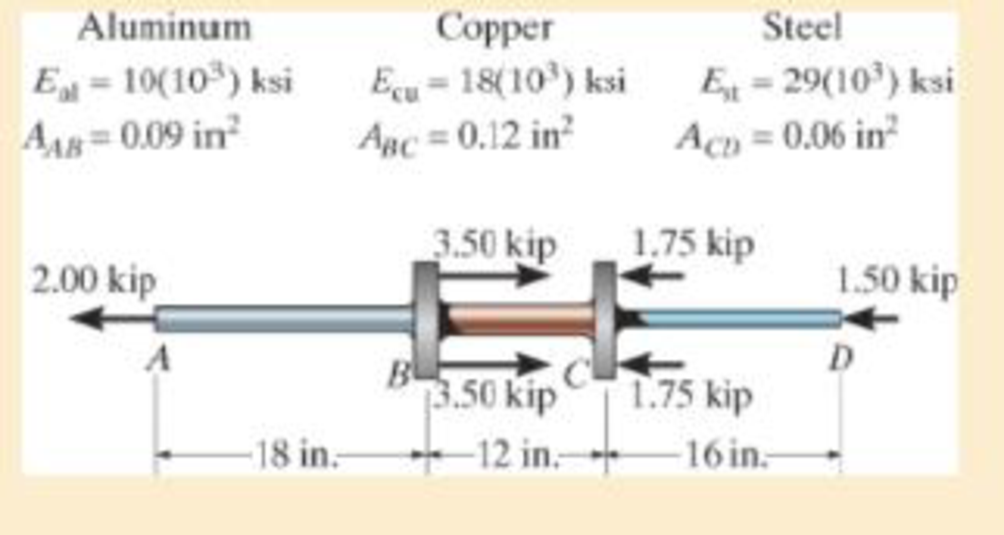
The composite shaft, consisting of aluminum, copper, and steel sections, is subjected to the loading shown. Determine the displacement of end A with respect to end D and the normal stress in each section. The cross-sectional area and modulus of elasticity for each section are shown in the figure. Neglect the size of the collars at B and C.
Expert Solution & Answer
Want to see the full answer?
Check out a sample textbook solution
Students have asked these similar questions
The composite shaft, consisting of aluminum, copper, and steel sections, is subjected to the loading shown. Determine the displacement of end A with respect to end D and the normal stress in each section. The cross-sectionalarea and modulus of elasticity for each section are shown in the figure. Neglect the size of the collars at B and C.
4.3 The composite shaft, consisting of aluminum, copper, and steel sections, is subjected to the loading
shown. Determine the displacement of end A with respect to end D and the normal stress in each
section. The cross-sectional area and modulus of elasticity for each section are shown in the figure.
Neglect the size of the collars at Band C.
3.50 kip
1.75 kip
1.50 kip
2.00 kip
Steel
BL
3.50 kip
1.75 kip
Aluminum
Copper
Est = 29 (10)³ Ksi
-18 in-
-12 in-
-16 in-
Ecu = 18 (10)3 Ksi
ABC = 0.12 in?
Eal = 10(10)³ Ksi
AcD = 0.09 6in²
= 0.09 in?
AAB
1.
The composite shaft, consisting of aluminum, copper,
and steel sections, is subjected to the loading shown.
Determine the displacement of B with respect to C and the
normal stress in each section. The cross-sectional area and
modulus of elasticity for each section are shown in the figure.
Neglect the size of the collars at B and C.
Aluminum
Eal = 70 GPa
AAB = 58 mm²
9 kN
A
Copper
Ecu = 126 GPa
ABC = 77 mm²
450 mm
16 kN
斤。
16 kN
-300 mm
BL
Steel
Est = 200 GPa
ACD = 39 mm²
8 kN
8 kN
-400 mm
7 kN
Chapter 4 Solutions
Mechanics of Materials
Ch. 4.2 - In each case, determine the internal normal force...Ch. 4.2 - Determine the internal normal force between...Ch. 4.2 - The post weighs 8kN/m. Determine the internal...Ch. 4.2 - The rod is subjected to an external axial force of...Ch. 4.2 - The rigid beam supports the load of 60 kN....Ch. 4.2 - The 20-mm-diameter A-36 steel rod is subjected to...Ch. 4.2 - Segments AB and CD of the assembly are solid...Ch. 4.2 - The 30-mm-diameter A992 steel rod is subjected to...Ch. 4.2 - If the 20-mm-diameter rod is made of A-36 steel...Ch. 4.2 - The 20-mm-diameter 2014-T6 aluminum rod is...
Ch. 4.2 - The 20-mm-diameter 2014-T6 aluminum rod is...Ch. 4.2 - Prob. 4.1PCh. 4.2 - The copper shaft is subjected to the axial loads...Ch. 4.2 - The composite shaft, consisting of aluminum,...Ch. 4.2 - The composite shaft, consisting of aluminum,...Ch. 4.2 - 4-5. The assembly consists of a steel rod CB and...Ch. 4.2 - 4-6. The bar has a cross-sectional area of 3 in2,...Ch. 4.2 - 4–7. If P1 = 50 kip and P2 = 150 kip, determine...Ch. 4.2 - *4-8. If the vertical displacements of end A of...Ch. 4.2 - The assembly consists of two 10-mm diameter red...Ch. 4.2 - The assembly consists of two 10-mm diameter red...Ch. 4.2 - The load is supported by the four 304 stainless...Ch. 4.2 - The load is supported by the four 304 stainless...Ch. 4.2 - The rigid bar is supported by the pin-connected...Ch. 4.2 - Prob. 4.14PCh. 4.2 - Prob. 4.15PCh. 4.2 - *4-16. The hanger consists of three 2014-T6...Ch. 4.2 - 4-17. The hanger consists of three 2014-T6...Ch. 4.2 - Prob. 4.18PCh. 4.2 - Prob. 4.19PCh. 4.2 - The assembly consists of three titanium...Ch. 4.2 - Prob. 4.21PCh. 4.2 - Prob. 4.22PCh. 4.2 - Prob. 4.23PCh. 4.2 - Determine the relative displacement of one end of...Ch. 4.2 - Prob. 4.25PCh. 4.2 - Prob. 4.26PCh. 4.2 - 4-27. The circular bar has a variable radius of r...Ch. 4.2 - Prob. 4.28PCh. 4.2 - Prob. 4.29PCh. 4.2 - Prob. 4.30PCh. 4.5 - 4-31. The concrete column is reinforced using four...Ch. 4.5 - Prob. 4.32PCh. 4.5 - 4-33. The steel pipe is filled with concrete and...Ch. 4.5 - If column AB is made from high strength precast...Ch. 4.5 - If column AB is made from high strength precast...Ch. 4.5 - Determine the support reactions at the rigid...Ch. 4.5 - If the supports at A and C are flexible and have a...Ch. 4.5 - Prob. 4.38PCh. 4.5 - Prob. 4.39PCh. 4.5 - Prob. 4.40PCh. 4.5 - The 2014-T6 aluminum rod AC is reinforced with the...Ch. 4.5 - The 2014-T6 aluminum rod AC is reinforced with the...Ch. 4.5 - The assembly consists of two red brass C83400...Ch. 4.5 - *4-44. The assembly consists of two red brass...Ch. 4.5 - Prob. 4.45PCh. 4.5 - If the gap between C and the rigid wall at D is...Ch. 4.5 - The support consists of a solid red brass C83400...Ch. 4.5 - If there are n fibers, each having a...Ch. 4.5 - Prob. 4.49PCh. 4.5 - Prob. 4.50PCh. 4.5 - Prob. 4.51PCh. 4.5 - Prob. 4.52PCh. 4.5 - 4-53. Each of the three A-36 steel wires has the...Ch. 4.5 - 4-54. The 200-kg load is suspended from three A-36...Ch. 4.5 - The three suspender bars are made of A992 steel...Ch. 4.5 - Prob. 4.56PCh. 4.5 - 4-57. The rigid bar is originally horizontal and...Ch. 4.5 - Prob. 4.58PCh. 4.5 - 4-59. Two identical rods AB and CD each have a...Ch. 4.5 - *4-60. The assembly consists of two posts AD and...Ch. 4.5 - Prob. 4.61PCh. 4.5 - Prob. 4.62PCh. 4.5 - Prob. 4.63PCh. 4.5 - Prob. 4.64PCh. 4.5 - 4-65. Initially the A-36 bolt shank fits snugly...Ch. 4.5 - Prob. 4.66PCh. 4.5 - Prob. 4.67PCh. 4.6 - The C83400-red-brass rod AB and 2014-T6- aluminum...Ch. 4.6 - The assembly has the diameters and material...Ch. 4.6 - The rod is made of A992 steel and has a diameter...Ch. 4.6 - Prob. 4.71PCh. 4.6 - Prob. 4.72PCh. 4.6 - The pipe is made of A992 steel and is connected to...Ch. 4.6 - The bronze C86100 pipe has an inner radius of 0.5...Ch. 4.6 - The 40-ft-long A-36 steel rails on a train track...Ch. 4.6 - The device is used to measure a change in...Ch. 4.6 - The bar has a cross-sectional area A, length L,...Ch. 4.6 - When the temperature is at 30C, the A-36 steel...Ch. 4.6 - When the temperature is at 30C, the A-36 steel...Ch. 4.6 - When the temperature is at 30C, the A-36 steel...Ch. 4.6 - The 50-mm-diameter cylinder is made from Am...Ch. 4.6 - The 50-mm-diameter cylinder is made from Am...Ch. 4.6 - The wires AB and AC are made of steel, and wire AD...Ch. 4.6 - The cylinder CD of the assembly is heated from T1...Ch. 4.6 - The cylinder CD of the assembly is heated from T1=...Ch. 4.6 - The metal strap has a thickness t and width w and...Ch. 4.9 - Determine the maximum normal stress developed in...Ch. 4.9 - If the allowable normal stress for the bar is...Ch. 4.9 - The steel bar has the dimensions shown. Determine...Ch. 4.9 - 4-90. Determine the maximum axial force P that can...Ch. 4.9 - Determine the maximum axial force P that can be...Ch. 4.9 - Determine the maximum normal stress developed in...Ch. 4.9 - Prob. 4.93PCh. 4.9 - 4-94. The resulting stress distribution along...Ch. 4.9 - Prob. 4.95PCh. 4.9 - *4-96. The 10-mm-diameter shank of the steel bolt...Ch. 4.9 - The weight is suspended from steel and aluminum...Ch. 4.9 - The bar has a cross-sectional area of 0.5 in2 and...Ch. 4.9 - Prob. 4.99PCh. 4.9 - *4-100. The rigid beam is supported by a pin at A...Ch. 4.9 - The rigid lever arm is supported by two A-36 steel...Ch. 4.9 - The rigid lever arm is supported by two A-36 steel...Ch. 4.9 - Prob. 4.103PCh. 4.9 - The rigid beam is supported by three 25-mm...Ch. 4.9 - The rigid beam is supported by three 25-mm...Ch. 4.9 - Prob. 4.106PCh. 4.9 - Prob. 4.107PCh. 4.9 - The rigid beam is supported by the three posts A,...Ch. 4.9 - The rigid beam is supported by the three posts A,...Ch. 4.9 - Prob. 4.110PCh. 4.9 - The bar having a diameter of 2 in. is fixed...Ch. 4.9 - Determine the elongation of the bar in Prob.4108...Ch. 4.9 - Prob. 4.113PCh. 4 - The assembly consists of two A992 steel bolts AB...Ch. 4 - The assembly shown consists of two A992 steel...Ch. 4 - The rods each have the same 25-mm diameter and...Ch. 4 - Two A992 steel pipes, each having a...Ch. 4 - The force P is applied to the bar, which is made...Ch. 4 - The 2014-T6 aluminum rod has a diameter of 0.5 in....Ch. 4 - The 2014-T6 aluminum rod has a diameter of 0.5 in....Ch. 4 - The rigid link is supported by a pin at A and two...Ch. 4 - The joint is made from three A992 steel plates...
Knowledge Booster


Learn more about
Need a deep-dive on the concept behind this application? Look no further. Learn more about this topic, mechanical-engineering and related others by exploring similar questions and additional content below.Similar questions
- The stepped shaft shown in the figure is supported by bearings at A and B. Determine the maximum stress in the shaft due to the applied couples. The shoulder fillet at the junction of each shaft has a radius of r = 6 mm.arrow_forwardThe following shaft is free at A and connected to a fixed support at C. The shaft has a solid circular cross section with radius equal to 25 mm. given the two external forces at section A: (a) Determine the internal loading components at section B. (b) Determine the combined shear stress at point P located on top of section B. (c) Determine the combined normal stress at point P.arrow_forwardThe cylindrical steel column has an outer diameter of 90 mm and inner diameter of 80 mm. The column is separated from the concrete foundation by a square bearing plate with the dimension of 160 mm x 160 mm. The working compressive and tensile stresses are 180 MPa and 200 MPa respectively, while the working bearing stress of concrete is 10 MPa. Find the largest force P that can be applied to the column. Sleel Concrete Foundation Bearing Planearrow_forward
- The composite shaft, consisting of aluminum, copper, and steel sections, is subjected to the loading shown. Determine the displacement of B with respect to C. The cross-sectional area and modulus of elasticity for eachsection are shown in the figure. Neglect the size of the collars at B and C.arrow_forwardThe bar in Figure has a constant width of 35 mm and a thickness of 10 mm. Determine the maximum average normal stress in the bar when it is subjected to the loading shown.arrow_forwardThe frame is loaded by a distributed load of intensity q as shown. Consider -25 in. only stress in the bars AC and BC. Each bar has a cross-section that is 0.75 in by 1.5 in. If the allowable normal stress is 5000 psi, determine the maximum allowable value for the distributed load intensity q. 40 in.arrow_forward
- The cylindrical steel column has an outer diameter of 4 in. and inner diameter of 3.5 in. The column is separated from the concrete foundation by a square bearing plate. The working compressive stress is 26 000 psi for the column, and the working bearing stress is 1200 psi for concrete. Find the largest force P that can be applied to the column. Express your answer in Ib. 4 in. 3.5 in. 4/4 7 in.arrow_forward4. The shaft below is hollow from A to B and solid from B to C. Determine the maximum shear stress in the shaft. The shaft has an outer diameter of 80mm and the thickness of the wall of the hollow segment is 10mm. Please note there are two different formula for solid and hollow shaft. 4 kN-m 2 kN-marrow_forwardThe cylinder for a hydraulic press has an inside diameter of 300 mm and an outside radius of 260 mm. Find the maximum shear stress in the cylinder for an internal pressure of (60 + 20) MPa.arrow_forward
- The vertical shaft with a diameter of d = 20 mm is supported by a thrust collar that rests on a 21-mm-thick plate. The thrust collar is 16-mm thick. Assume that the load P causes a compressive stress of 190 MPa in the shaft. If the bearing stress between the thrust collar and the plate is limited to 35 MPa, determine the minimum outer diameter Dcollar that must be used for the thrust collar. Thrust collar area Plate Thrust collar d Dcollararrow_forwardThe shaft consists of three concentric tubes, each made from the same material and having inner and outer radii as given below. Length of shaft is 2m. One end is fixed to the wall and to the other end a disc is attached. If a torque of T =800 N.m is applied at the disc end, determine the maximum shear stress in the shaft. 1. Inner tube: r; = 20mm, r, = 25 mm 2. Center tube: r; = 26 mm, r. = 30 mm 3. Outer tube: r = 32mm, r, = 38mmarrow_forwardThe 40-mm diameter solid shaft ACBD is supported by two bearings at A and B. Due to the transmission of power to and from the shaft, the belts of the pulleys are subjected to the tension forces shown in the figure below. 1-Draw the moment and shear diagrams on the y z and y x planes 2-Determine the location and magnitude of the maximum bending (normal) stress. Hint draw the shaft cross section at that location and think of the associated stresses. 0.050 m 300 N 0.250 m 200 N 550 N 0.250 m 400 N 150m D 0.075 marrow_forward
arrow_back_ios
SEE MORE QUESTIONS
arrow_forward_ios
Recommended textbooks for you
 Mechanics of Materials (MindTap Course List)Mechanical EngineeringISBN:9781337093347Author:Barry J. Goodno, James M. GerePublisher:Cengage Learning
Mechanics of Materials (MindTap Course List)
Mechanical Engineering
ISBN:9781337093347
Author:Barry J. Goodno, James M. Gere
Publisher:Cengage Learning
Everything About COMBINED LOADING in 10 Minutes! Mechanics of Materials; Author: Less Boring Lectures;https://www.youtube.com/watch?v=N-PlI900hSg;License: Standard youtube license