
Mechanics of Materials
9th Edition
ISBN: 9780133254426
Author: Russell C. Hibbeler
Publisher: Prentice Hall
expand_more
expand_more
format_list_bulleted
Concept explainers
Videos
Textbook Question
Chapter 4.2, Problem 4.20P
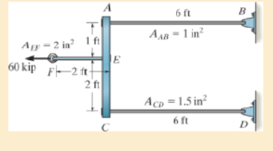
The assembly consists of three titanium (Ti-6A1-4V) rods and a rigid bar AC. The cross-sectional area of each rod is given in the figure. If a force of 60 kip is applied to the ring F, determine the horizontal displacement of point F.
Expert Solution & Answer
Want to see the full answer?
Check out a sample textbook solution
Students have asked these similar questions
The assembly consists of three titanium (Ti-6A1-
4V) rods and a rigid bar AC. The cross-section area
of each rod is given in the figure. If a force of 60 kip
is applied o the ring F, determine the horizontal
displacement of point F.
Hint: Refer to the textbook appendix for material
properties.
AEF 2 in² 1 ft
=
60 kip F-2 ft-
2 ft
A
C
6 ft
B
AAB
=
1 in²
E
ACD = 1.5 in²
6 ft
D
Both portions of the rod ABC are made of an aluminum for which E = 70 GPa.
What is the corresponding displacement at B in millimeter if P = 57 kN and Q = 397 kN?
The assembly consists of three steel rods (E=13 x 106 psi) and a rigid bar AC. The
cross-sectional area of each rod is given in Figure 1. If a force of 6.5 kip is applied to the
ring F, determine the horizontal displacement of point F.
D
4 ft
AcD = 1.5 in?
2 ft
F
E
1 ft
6.5 kip
1 ft AEF = 2.1 in?
A AB = 1.3 in?
6 ft
Figure 1
Chapter 4 Solutions
Mechanics of Materials
Ch. 4.2 - In each case, determine the internal normal force...Ch. 4.2 - Determine the internal normal force between...Ch. 4.2 - The post weighs 8kN/m. Determine the internal...Ch. 4.2 - The rod is subjected to an external axial force of...Ch. 4.2 - The rigid beam supports the load of 60 kN....Ch. 4.2 - The 20-mm-diameter A-36 steel rod is subjected to...Ch. 4.2 - Segments AB and CD of the assembly are solid...Ch. 4.2 - The 30-mm-diameter A992 steel rod is subjected to...Ch. 4.2 - If the 20-mm-diameter rod is made of A-36 steel...Ch. 4.2 - The 20-mm-diameter 2014-T6 aluminum rod is...
Ch. 4.2 - The 20-mm-diameter 2014-T6 aluminum rod is...Ch. 4.2 - Prob. 4.1PCh. 4.2 - The copper shaft is subjected to the axial loads...Ch. 4.2 - The composite shaft, consisting of aluminum,...Ch. 4.2 - The composite shaft, consisting of aluminum,...Ch. 4.2 - 4-5. The assembly consists of a steel rod CB and...Ch. 4.2 - 4-6. The bar has a cross-sectional area of 3 in2,...Ch. 4.2 - 4–7. If P1 = 50 kip and P2 = 150 kip, determine...Ch. 4.2 - *4-8. If the vertical displacements of end A of...Ch. 4.2 - The assembly consists of two 10-mm diameter red...Ch. 4.2 - The assembly consists of two 10-mm diameter red...Ch. 4.2 - The load is supported by the four 304 stainless...Ch. 4.2 - The load is supported by the four 304 stainless...Ch. 4.2 - The rigid bar is supported by the pin-connected...Ch. 4.2 - Prob. 4.14PCh. 4.2 - Prob. 4.15PCh. 4.2 - *4-16. The hanger consists of three 2014-T6...Ch. 4.2 - 4-17. The hanger consists of three 2014-T6...Ch. 4.2 - Prob. 4.18PCh. 4.2 - Prob. 4.19PCh. 4.2 - The assembly consists of three titanium...Ch. 4.2 - Prob. 4.21PCh. 4.2 - Prob. 4.22PCh. 4.2 - Prob. 4.23PCh. 4.2 - Determine the relative displacement of one end of...Ch. 4.2 - Prob. 4.25PCh. 4.2 - Prob. 4.26PCh. 4.2 - 4-27. The circular bar has a variable radius of r...Ch. 4.2 - Prob. 4.28PCh. 4.2 - Prob. 4.29PCh. 4.2 - Prob. 4.30PCh. 4.5 - 4-31. The concrete column is reinforced using four...Ch. 4.5 - Prob. 4.32PCh. 4.5 - 4-33. The steel pipe is filled with concrete and...Ch. 4.5 - If column AB is made from high strength precast...Ch. 4.5 - If column AB is made from high strength precast...Ch. 4.5 - Determine the support reactions at the rigid...Ch. 4.5 - If the supports at A and C are flexible and have a...Ch. 4.5 - Prob. 4.38PCh. 4.5 - Prob. 4.39PCh. 4.5 - Prob. 4.40PCh. 4.5 - The 2014-T6 aluminum rod AC is reinforced with the...Ch. 4.5 - The 2014-T6 aluminum rod AC is reinforced with the...Ch. 4.5 - The assembly consists of two red brass C83400...Ch. 4.5 - *4-44. The assembly consists of two red brass...Ch. 4.5 - Prob. 4.45PCh. 4.5 - If the gap between C and the rigid wall at D is...Ch. 4.5 - The support consists of a solid red brass C83400...Ch. 4.5 - If there are n fibers, each having a...Ch. 4.5 - Prob. 4.49PCh. 4.5 - Prob. 4.50PCh. 4.5 - Prob. 4.51PCh. 4.5 - Prob. 4.52PCh. 4.5 - 4-53. Each of the three A-36 steel wires has the...Ch. 4.5 - 4-54. The 200-kg load is suspended from three A-36...Ch. 4.5 - The three suspender bars are made of A992 steel...Ch. 4.5 - Prob. 4.56PCh. 4.5 - 4-57. The rigid bar is originally horizontal and...Ch. 4.5 - Prob. 4.58PCh. 4.5 - 4-59. Two identical rods AB and CD each have a...Ch. 4.5 - *4-60. The assembly consists of two posts AD and...Ch. 4.5 - Prob. 4.61PCh. 4.5 - Prob. 4.62PCh. 4.5 - Prob. 4.63PCh. 4.5 - Prob. 4.64PCh. 4.5 - 4-65. Initially the A-36 bolt shank fits snugly...Ch. 4.5 - Prob. 4.66PCh. 4.5 - Prob. 4.67PCh. 4.6 - The C83400-red-brass rod AB and 2014-T6- aluminum...Ch. 4.6 - The assembly has the diameters and material...Ch. 4.6 - The rod is made of A992 steel and has a diameter...Ch. 4.6 - Prob. 4.71PCh. 4.6 - Prob. 4.72PCh. 4.6 - The pipe is made of A992 steel and is connected to...Ch. 4.6 - The bronze C86100 pipe has an inner radius of 0.5...Ch. 4.6 - The 40-ft-long A-36 steel rails on a train track...Ch. 4.6 - The device is used to measure a change in...Ch. 4.6 - The bar has a cross-sectional area A, length L,...Ch. 4.6 - When the temperature is at 30C, the A-36 steel...Ch. 4.6 - When the temperature is at 30C, the A-36 steel...Ch. 4.6 - When the temperature is at 30C, the A-36 steel...Ch. 4.6 - The 50-mm-diameter cylinder is made from Am...Ch. 4.6 - The 50-mm-diameter cylinder is made from Am...Ch. 4.6 - The wires AB and AC are made of steel, and wire AD...Ch. 4.6 - The cylinder CD of the assembly is heated from T1...Ch. 4.6 - The cylinder CD of the assembly is heated from T1=...Ch. 4.6 - The metal strap has a thickness t and width w and...Ch. 4.9 - Determine the maximum normal stress developed in...Ch. 4.9 - If the allowable normal stress for the bar is...Ch. 4.9 - The steel bar has the dimensions shown. Determine...Ch. 4.9 - 4-90. Determine the maximum axial force P that can...Ch. 4.9 - Determine the maximum axial force P that can be...Ch. 4.9 - Determine the maximum normal stress developed in...Ch. 4.9 - Prob. 4.93PCh. 4.9 - 4-94. The resulting stress distribution along...Ch. 4.9 - Prob. 4.95PCh. 4.9 - *4-96. The 10-mm-diameter shank of the steel bolt...Ch. 4.9 - The weight is suspended from steel and aluminum...Ch. 4.9 - The bar has a cross-sectional area of 0.5 in2 and...Ch. 4.9 - Prob. 4.99PCh. 4.9 - *4-100. The rigid beam is supported by a pin at A...Ch. 4.9 - The rigid lever arm is supported by two A-36 steel...Ch. 4.9 - The rigid lever arm is supported by two A-36 steel...Ch. 4.9 - Prob. 4.103PCh. 4.9 - The rigid beam is supported by three 25-mm...Ch. 4.9 - The rigid beam is supported by three 25-mm...Ch. 4.9 - Prob. 4.106PCh. 4.9 - Prob. 4.107PCh. 4.9 - The rigid beam is supported by the three posts A,...Ch. 4.9 - The rigid beam is supported by the three posts A,...Ch. 4.9 - Prob. 4.110PCh. 4.9 - The bar having a diameter of 2 in. is fixed...Ch. 4.9 - Determine the elongation of the bar in Prob.4108...Ch. 4.9 - Prob. 4.113PCh. 4 - The assembly consists of two A992 steel bolts AB...Ch. 4 - The assembly shown consists of two A992 steel...Ch. 4 - The rods each have the same 25-mm diameter and...Ch. 4 - Two A992 steel pipes, each having a...Ch. 4 - The force P is applied to the bar, which is made...Ch. 4 - The 2014-T6 aluminum rod has a diameter of 0.5 in....Ch. 4 - The 2014-T6 aluminum rod has a diameter of 0.5 in....Ch. 4 - The rigid link is supported by a pin at A and two...Ch. 4 - The joint is made from three A992 steel plates...
Knowledge Booster


Learn more about
Need a deep-dive on the concept behind this application? Look no further. Learn more about this topic, mechanical-engineering and related others by exploring similar questions and additional content below.Similar questions
- Four pulleys are attached to the 50-mm-diameter aluminum shaft. If torques are applied to the pulleys as shown in the figure, determine the angle of rotation of pulley D relative to pulley A. Use G = 28 GPa for aluminum.arrow_forwardThe rod ABC having a constant AE is subjected to external forces at points B and C, as shown. What is the required value of the P so that the displacement of end C will be zero?arrow_forward2-16. The tapered steel bar shown in the figure is cut out from a steel plate 25 mm thick and is welded at the top to a rigid structure. Find the deflection of the end A caused by the force of 40 kN applied at B. Consider the origin of the coordinate axes at the point of intersection of the sloping lines. E = 210 GN/m². Ans: 0.093 mm. 150 mm 1.5 m 40 kN B 1.5 m 50 mm PROB. 2 – 16arrow_forward
- The assembly consists of three titanium (Ti-6A1-4V) rods and a rigid bar AC. 6 ft AAB = 1 in? Agr = 2 in? 1 f HE F- 2 ftH 2 ft P Acp = 1.5 in? 6 ft The cross-sectional area of each rod is given in the figure. A force of P = 51 kip is applied to the ring F. Part A Determine the horizontal displacement of point F. Use E = 17.4(10³) ksi. Express your answer to three significant figures and include appropriate units. ? Value Unitsarrow_forwardThe shaft is supported at its ends two bearings A and B and is subjected to the forces applied to the pulleys fixed to the shaft. (Figure 1) The T₁ = 410-N forces act in the -z direction and the 200-N and 80-N forces act in the +y direction. The journal bearings at A and B exert only y and components of force on the shaft. Figure 200 mm 300 mm 150 mm, 150 mm 200 mm 400 mm B 200 N 80 N 80 N 200 N < 1 of 1 Determine the resultant normal force on the cross section at C Express your answer to three significant figures and include appropriate units. Nc= Submit Part B (Vc)y= Submit Part C Value Determine the resultant shear force in the y direction on the cross section at C Express your answer to three significant figures and include appropriate units. (Vc)= = Request Answer 4 ▬▬ μÀ 4 Value Request Answer μà → ⒸIE ? Value Units Determine the resultant shear force in the direction on the cross section at C Express your answer to three significant figures and include appropriate units. Ć IE ?…arrow_forwardThe steel box wrench (E=29,000ksi, v=0.32) is loaded with a 40-lb horizontal force and a 25-lb vertical force. Find the following for an element located at point B on Section a-a: 24 in. 1. The non-vanishing resultant internal moments on section a-a are which of the following? 4 in. a. (160 i- 600 j+960 k)in · Ib b. (-160 i+600 j+960 k ) in · lb c. (-960 i+160 j+600 k)in - lb d. (-960 i -160 ј-600 k)in-lb a e. none of the above 2. The normal and shear force components on section a-a are: a. V, = 65lb;V, = 40lb; N¸ = 25lb b. V, = 0;V, =40lb; N, = 25lb c. V, = 64;V, = 25lb; N, = 40lb d. V, =0;V, =-40lb; N¸ = -25lb e. none of the above 3. The non-vanishing stress components at point B are: 0̟ =1.60; t =-4.89ksi; а. 0, =-4.89; 7 =3.60ksi; 0, = 2.50ksi; T, d. o, = 4.91ksi; t =-4.89ksi; b. с. =-4.89ksi; е. none of the above 4. The principal stresses at point B from most tensile to most compressive are: O1,02,0; =4.16,–0.8,–5.76 b. o,,0,,0, =5.76,0,–4.16 а. O1,02,0; =1.9,-2.45,-6.8 с. d.…arrow_forward
- The shaft is supported at its ends by two bearings AA and BB and is subjected to the forces applied to the pulleys fixed to the shaft. (Figure 1) The T1=T1= 585-NN forces act in the -zz direction and the 200-NN and 80-NN forces act in the +yy direction. The journal bearings at AA and BB exert only yy and zz components of force on the shaft. Part A Determine the resultant normal force on the cross section at CC. Express your answer to three significant figures and include appropriate units. NC= values ? NC= units? Determine the resultant shear force in the yy direction on the cross section at CC . Express your answer to three significant figures and include appropriate units. (VC)y Values ? (VC)y units ?arrow_forwardShow the zero force members on the figure (label them on the figure and list them on the side). (Note: you don't have to solve the entire structure) D E 60 kips В F A M L K J G Н 180 kips 120 kipsarrow_forwardThe rigid bar AB and CD are supported by pins at A and D. the vertical rods are made of aluminum and bronze. Determine the vertical displacement of the point where the force P= 10 kips is applied. Neglect the weight of the members.arrow_forward
- Determine the horizontal displacement of end point D of the steel rod shown in the figure. E = 200 GPa A = 200 mm² A = 600 mm² A B ka 300 kN 0.3 m Your answer: 0.3 m 0.25 mm to the left 0.25 mm to the right 1.25 mm to the right 1.25 mm to the left 1.75 mm to the right C 200 KN 0.4 m- D 100 kNarrow_forward3. At temperature T₁, the two rigidly connected rods just fit the rigid supports. If both sections are identical except for the diameter, prove that the following equations are true when temperature rises to T₂. a. F= b. OAB C. OBC A x(T₂-T₁)лd²E 20 x(T₂-T₁)E 5 9x(T₂-T₁)E 5 -1/2- d B 1/12- d Carrow_forward3. The rigid bars AB and CD are supported by pins at A and D. The vertical rods are made of aluminum and bronze. Determine the vertical displacement of the point where the force P = 10 kips is applied. Neglect the weights of the members. Aluminum L= 4 f A=0.75 in. E= 10x 10 psi B 4 ft Bronze L= 5 A A=0.25 in.? E= 12x 10 psi 2 ft--2 ft-→arrow_forward
arrow_back_ios
SEE MORE QUESTIONS
arrow_forward_ios
Recommended textbooks for you
 Mechanics of Materials (MindTap Course List)Mechanical EngineeringISBN:9781337093347Author:Barry J. Goodno, James M. GerePublisher:Cengage Learning
Mechanics of Materials (MindTap Course List)
Mechanical Engineering
ISBN:9781337093347
Author:Barry J. Goodno, James M. Gere
Publisher:Cengage Learning
Power Transmission; Author: Terry Brown Mechanical Engineering;https://www.youtube.com/watch?v=YVm4LNVp1vA;License: Standard Youtube License