
Mechanics of Materials
9th Edition
ISBN: 9780133254426
Author: Russell C. Hibbeler
Publisher: Prentice Hall
expand_more
expand_more
format_list_bulleted
Concept explainers
Videos
Textbook Question
Chapter 4.2, Problem 4.24P
Determine the relative displacement of one end of the tapered plate with respect to the other end when it is subjected to an axial load P.
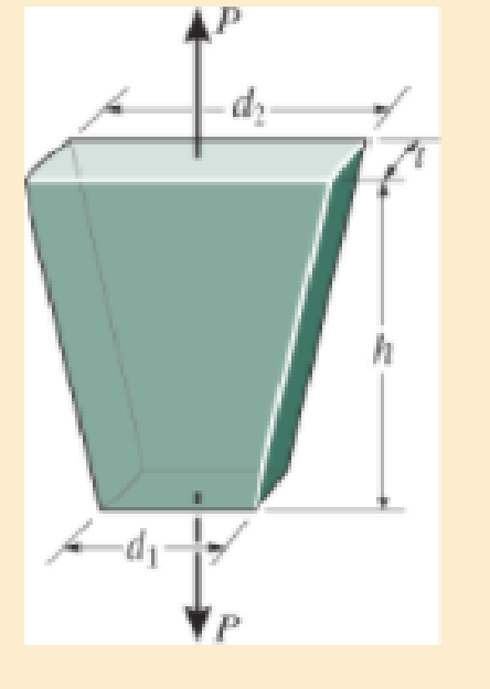
Prob. 4–24
Expert Solution & Answer
Want to see the full answer?
Check out a sample textbook solution
Students have asked these similar questions
The assembly below consists of a steel rod CB and an aluminium rod BA, each having a diameter of 12 mm.
If the rod is subjected to the axial loadings at A and at the coupling B, determine the displacement of the coupling B and the end A.
The unstretched length of each segment is shown below. Neglect the size of the connections at B and C, and assume that they are rigid. Est = 200 GPa, Eal = 70 GPa.
*3-8. The strut is supported by a pin at C and an A-36
steel guy wire AB. If the wire has 'a diameter of 5 mm,
determine how much it stretches when the distributed load
acts on the strut.
60
3.4 kN/m
2.7 m
The two solid steel shafts are connected by gears C and F and
9 in.
2,5 in.
supported by smooth bearings at B, D, and E. The upper shaft
is fixed at G. If the shear modulus is G = 11 x 10° ksi, determine
the angle of rotation of end A when the torque of 700 lb - ft is
аpplied.
E
1.75 in.
-3 in.
4 ft
B
700 lb ft
5 ft
Chapter 4 Solutions
Mechanics of Materials
Ch. 4.2 - In each case, determine the internal normal force...Ch. 4.2 - Determine the internal normal force between...Ch. 4.2 - The post weighs 8kN/m. Determine the internal...Ch. 4.2 - The rod is subjected to an external axial force of...Ch. 4.2 - The rigid beam supports the load of 60 kN....Ch. 4.2 - The 20-mm-diameter A-36 steel rod is subjected to...Ch. 4.2 - Segments AB and CD of the assembly are solid...Ch. 4.2 - The 30-mm-diameter A992 steel rod is subjected to...Ch. 4.2 - If the 20-mm-diameter rod is made of A-36 steel...Ch. 4.2 - The 20-mm-diameter 2014-T6 aluminum rod is...
Ch. 4.2 - The 20-mm-diameter 2014-T6 aluminum rod is...Ch. 4.2 - Prob. 4.1PCh. 4.2 - The copper shaft is subjected to the axial loads...Ch. 4.2 - The composite shaft, consisting of aluminum,...Ch. 4.2 - The composite shaft, consisting of aluminum,...Ch. 4.2 - 4-5. The assembly consists of a steel rod CB and...Ch. 4.2 - 4-6. The bar has a cross-sectional area of 3 in2,...Ch. 4.2 - 4–7. If P1 = 50 kip and P2 = 150 kip, determine...Ch. 4.2 - *4-8. If the vertical displacements of end A of...Ch. 4.2 - The assembly consists of two 10-mm diameter red...Ch. 4.2 - The assembly consists of two 10-mm diameter red...Ch. 4.2 - The load is supported by the four 304 stainless...Ch. 4.2 - The load is supported by the four 304 stainless...Ch. 4.2 - The rigid bar is supported by the pin-connected...Ch. 4.2 - Prob. 4.14PCh. 4.2 - Prob. 4.15PCh. 4.2 - *4-16. The hanger consists of three 2014-T6...Ch. 4.2 - 4-17. The hanger consists of three 2014-T6...Ch. 4.2 - Prob. 4.18PCh. 4.2 - Prob. 4.19PCh. 4.2 - The assembly consists of three titanium...Ch. 4.2 - Prob. 4.21PCh. 4.2 - Prob. 4.22PCh. 4.2 - Prob. 4.23PCh. 4.2 - Determine the relative displacement of one end of...Ch. 4.2 - Prob. 4.25PCh. 4.2 - Prob. 4.26PCh. 4.2 - 4-27. The circular bar has a variable radius of r...Ch. 4.2 - Prob. 4.28PCh. 4.2 - Prob. 4.29PCh. 4.2 - Prob. 4.30PCh. 4.5 - 4-31. The concrete column is reinforced using four...Ch. 4.5 - Prob. 4.32PCh. 4.5 - 4-33. The steel pipe is filled with concrete and...Ch. 4.5 - If column AB is made from high strength precast...Ch. 4.5 - If column AB is made from high strength precast...Ch. 4.5 - Determine the support reactions at the rigid...Ch. 4.5 - If the supports at A and C are flexible and have a...Ch. 4.5 - Prob. 4.38PCh. 4.5 - Prob. 4.39PCh. 4.5 - Prob. 4.40PCh. 4.5 - The 2014-T6 aluminum rod AC is reinforced with the...Ch. 4.5 - The 2014-T6 aluminum rod AC is reinforced with the...Ch. 4.5 - The assembly consists of two red brass C83400...Ch. 4.5 - *4-44. The assembly consists of two red brass...Ch. 4.5 - Prob. 4.45PCh. 4.5 - If the gap between C and the rigid wall at D is...Ch. 4.5 - The support consists of a solid red brass C83400...Ch. 4.5 - If there are n fibers, each having a...Ch. 4.5 - Prob. 4.49PCh. 4.5 - Prob. 4.50PCh. 4.5 - Prob. 4.51PCh. 4.5 - Prob. 4.52PCh. 4.5 - 4-53. Each of the three A-36 steel wires has the...Ch. 4.5 - 4-54. The 200-kg load is suspended from three A-36...Ch. 4.5 - The three suspender bars are made of A992 steel...Ch. 4.5 - Prob. 4.56PCh. 4.5 - 4-57. The rigid bar is originally horizontal and...Ch. 4.5 - Prob. 4.58PCh. 4.5 - 4-59. Two identical rods AB and CD each have a...Ch. 4.5 - *4-60. The assembly consists of two posts AD and...Ch. 4.5 - Prob. 4.61PCh. 4.5 - Prob. 4.62PCh. 4.5 - Prob. 4.63PCh. 4.5 - Prob. 4.64PCh. 4.5 - 4-65. Initially the A-36 bolt shank fits snugly...Ch. 4.5 - Prob. 4.66PCh. 4.5 - Prob. 4.67PCh. 4.6 - The C83400-red-brass rod AB and 2014-T6- aluminum...Ch. 4.6 - The assembly has the diameters and material...Ch. 4.6 - The rod is made of A992 steel and has a diameter...Ch. 4.6 - Prob. 4.71PCh. 4.6 - Prob. 4.72PCh. 4.6 - The pipe is made of A992 steel and is connected to...Ch. 4.6 - The bronze C86100 pipe has an inner radius of 0.5...Ch. 4.6 - The 40-ft-long A-36 steel rails on a train track...Ch. 4.6 - The device is used to measure a change in...Ch. 4.6 - The bar has a cross-sectional area A, length L,...Ch. 4.6 - When the temperature is at 30C, the A-36 steel...Ch. 4.6 - When the temperature is at 30C, the A-36 steel...Ch. 4.6 - When the temperature is at 30C, the A-36 steel...Ch. 4.6 - The 50-mm-diameter cylinder is made from Am...Ch. 4.6 - The 50-mm-diameter cylinder is made from Am...Ch. 4.6 - The wires AB and AC are made of steel, and wire AD...Ch. 4.6 - The cylinder CD of the assembly is heated from T1...Ch. 4.6 - The cylinder CD of the assembly is heated from T1=...Ch. 4.6 - The metal strap has a thickness t and width w and...Ch. 4.9 - Determine the maximum normal stress developed in...Ch. 4.9 - If the allowable normal stress for the bar is...Ch. 4.9 - The steel bar has the dimensions shown. Determine...Ch. 4.9 - 4-90. Determine the maximum axial force P that can...Ch. 4.9 - Determine the maximum axial force P that can be...Ch. 4.9 - Determine the maximum normal stress developed in...Ch. 4.9 - Prob. 4.93PCh. 4.9 - 4-94. The resulting stress distribution along...Ch. 4.9 - Prob. 4.95PCh. 4.9 - *4-96. The 10-mm-diameter shank of the steel bolt...Ch. 4.9 - The weight is suspended from steel and aluminum...Ch. 4.9 - The bar has a cross-sectional area of 0.5 in2 and...Ch. 4.9 - Prob. 4.99PCh. 4.9 - *4-100. The rigid beam is supported by a pin at A...Ch. 4.9 - The rigid lever arm is supported by two A-36 steel...Ch. 4.9 - The rigid lever arm is supported by two A-36 steel...Ch. 4.9 - Prob. 4.103PCh. 4.9 - The rigid beam is supported by three 25-mm...Ch. 4.9 - The rigid beam is supported by three 25-mm...Ch. 4.9 - Prob. 4.106PCh. 4.9 - Prob. 4.107PCh. 4.9 - The rigid beam is supported by the three posts A,...Ch. 4.9 - The rigid beam is supported by the three posts A,...Ch. 4.9 - Prob. 4.110PCh. 4.9 - The bar having a diameter of 2 in. is fixed...Ch. 4.9 - Determine the elongation of the bar in Prob.4108...Ch. 4.9 - Prob. 4.113PCh. 4 - The assembly consists of two A992 steel bolts AB...Ch. 4 - The assembly shown consists of two A992 steel...Ch. 4 - The rods each have the same 25-mm diameter and...Ch. 4 - Two A992 steel pipes, each having a...Ch. 4 - The force P is applied to the bar, which is made...Ch. 4 - The 2014-T6 aluminum rod has a diameter of 0.5 in....Ch. 4 - The 2014-T6 aluminum rod has a diameter of 0.5 in....Ch. 4 - The rigid link is supported by a pin at A and two...Ch. 4 - The joint is made from three A992 steel plates...
Knowledge Booster


Learn more about
Need a deep-dive on the concept behind this application? Look no further. Learn more about this topic, mechanical-engineering and related others by exploring similar questions and additional content below.Similar questions
- *4-32. The column is constructed from high-strength concrete and four A-36 steel reinforcing rods. If it is subjected to an axial force of 800 kN, determine the required diameter of each rod so that one-fourth of the load is carried by the steel and three-fourths by the concrete. Est=200 GPa, Ec=25 GPa. 800 KN 300 mm 300 mm Probs. 4-31/32arrow_forward•4-33. The steel pipe is filled with concrete and subjected to a compressive force of 80 kN. Determine the average normal stress in the concrete and the steel due to this loading. The pipe has an outer diameter of 80 mm and an inner diameter of 70 mm. E = 200 GPa, E. = 24 GPa. 80 kN 500 mmarrow_forward4–3. The composite shaft, consisting of aluminum, copper, and steel sections, is subjected to the loading shown. Determine the displacement of end A with respect to end D and the normal stress in each section. The cross-sectional area and modulus of elasticity for each section are shown in the figure. Neglect the size of the collars at B and C. *4–4. Determine the displacement of B with respect to C of the composite shaft in Prob. 4–3.arrow_forward
- The assembly consists of a steel rod CB and an aluminum rod BA, each having a diameter of 15 mm. The rod is subjected to the axial loadings at A and at the coupling B. If after applying the load coupling B displaced 1.1 mm to the right, determine the change in the dimension of the cross section of steel rod CB. The unstretched length of each segment is shown in the figure. Neglect the size of the connections at B and C, and assume that they are rigid. Est = 200 GPa Vst = 0.32 %3D В A 20 kN 7 kN 3 m - 2 m·arrow_forwardThe truss is made of three A-36 steel members, each having a cross-sectional area of 400 mm2. Determine the horizontal displacement of the roller at C when P = 8 kN.arrow_forward4-111. The bar having a diameter of 50 mm is fixed connected at its ends and supports the axial load P. If the material is elastic perfectly plastic as shown by the stress-strain diagram, determine the smallest load Pneeded to cause segment CB to yield. If this load is released, determine the permanent displacement of point C. |C B -0.6 m- -0.9 m- o (MPa) 140 - E (mm/mm) 0.001arrow_forward
- The steel shaft has a diameter of 50 mm and is fixed at end A and turn free at end B. If it is subjected to the couple, determine the maximum shear stress in regions AC and CB of the shaft. G4 = 75 GPa. 3 kN A 3 kN 400 mm 50 mm 50 mm B 600 mmarrow_forward4-1. The copper shaft is subjected to the axial loads shown. Determine the displacement of end A with respect to end D. The diameters of each segment are dAB = 3 in., dBc = 2 in., and dcD = 1 in. Take Ecu = 18(10³) ksi. -50 in.- 75 in. 60 in. 6 kip A 2 kip B2 kip Prob. 4-1 C 3 kip D 1 kiparrow_forwardDetermine the moment M that will produce a maximum stress of 70 MPa on the cross-section. 12 mm -75 mm- -12 mm 12 mm B 75 mm 250 mm -- 12 mmarrow_forward
- 6-70. The strut on the utility pole supports the cable having a weight of 600 lb. Determine the absolute maximum bending stress in the strut if A, B, and C are assumed to be pinned. Problem 6-70 1.5 ft C A -2 ft - 4 ft B 2 in. I 600 lb 4 in.arrow_forward*4-20. The assembly consists of three titanium (Ti-6A1-4V) rods and a rigid bar AC. The cross-sectional area of each rod is given in the figure. If a force of 60 kip horizontal displacement of point F. is applied to the ring F, determine the AF-2 in² 1 ft 60 kip F-2 ft 2 ft E E 6 ft AAB-1 in² Acp-1.5 in² 6 ftarrow_forward3-31. The shear stress-strain diagram for a steel alloy is shown in the figure. If a bolt having a diameter of 0.75 in. is made of this material and used in the double lap joint, determine the modulus of elasticity E and the force P required to cause the material to yield. Take v = 0.3. P= 7(ksi) 60 0.00545 Prob. 3-31 P/2 P/2 y(rad)arrow_forward
arrow_back_ios
SEE MORE QUESTIONS
arrow_forward_ios
Recommended textbooks for you
 Elements Of ElectromagneticsMechanical EngineeringISBN:9780190698614Author:Sadiku, Matthew N. O.Publisher:Oxford University Press
 Mechanics of Materials (10th Edition)Mechanical EngineeringISBN:9780134319650Author:Russell C. HibbelerPublisher:PEARSON
 Thermodynamics: An Engineering ApproachMechanical EngineeringISBN:9781259822674Author:Yunus A. Cengel Dr., Michael A. BolesPublisher:McGraw-Hill Education
 Control Systems EngineeringMechanical EngineeringISBN:9781118170519Author:Norman S. NisePublisher:WILEY
 Mechanics of Materials (MindTap Course List)Mechanical EngineeringISBN:9781337093347Author:Barry J. Goodno, James M. GerePublisher:Cengage Learning
 Engineering Mechanics: StaticsMechanical EngineeringISBN:9781118807330Author:James L. Meriam, L. G. Kraige, J. N. BoltonPublisher:WILEY
Elements Of Electromagnetics
Mechanical Engineering
ISBN:9780190698614
Author:Sadiku, Matthew N. O.
Publisher:Oxford University Press
Mechanics of Materials (10th Edition)
Mechanical Engineering
ISBN:9780134319650
Author:Russell C. Hibbeler
Publisher:PEARSON
Thermodynamics: An Engineering Approach
Mechanical Engineering
ISBN:9781259822674
Author:Yunus A. Cengel Dr., Michael A. Boles
Publisher:McGraw-Hill Education
Control Systems Engineering
Mechanical Engineering
ISBN:9781118170519
Author:Norman S. Nise
Publisher:WILEY
Mechanics of Materials (MindTap Course List)
Mechanical Engineering
ISBN:9781337093347
Author:Barry J. Goodno, James M. Gere
Publisher:Cengage Learning
Engineering Mechanics: Statics
Mechanical Engineering
ISBN:9781118807330
Author:James L. Meriam, L. G. Kraige, J. N. Bolton
Publisher:WILEY
EVERYTHING on Axial Loading Normal Stress in 10 MINUTES - Mechanics of Materials; Author: Less Boring Lectures;https://www.youtube.com/watch?v=jQ-fNqZWrNg;License: Standard YouTube License, CC-BY