
Mechanics of Materials (MindTap Course List)
9th Edition
ISBN: 9781337093347
Author: Barry J. Goodno, James M. Gere
Publisher: Cengage Learning
expand_more
expand_more
format_list_bulleted
Concept explainers
Videos
Textbook Question
Chapter 4, Problem 4.5.33P
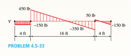
The shear-force diagram for a beam is shown in the figure. Assuming that no couples act as loads on the beam, determine the forces acting on the beam and draw the bending-moment diagram.
Expert Solution & Answer

Trending nowThis is a popular solution!

Students have asked these similar questions
The uniform beam with a mass of 500-kg is subjected to three external loads as shown in the figure. Draw the shear force and bending moment diagrams
please answer
The shear-force diagram for a beam is shown in the figure. Assuming that no couples act as loads on the beam, determine the forces acting on the beam and draw the bending-moment diagram.
The simply supported beam as shown in the figure supports a concentrated force of 30 kN at B and a torque of 40 kN at D. Show the diagrams of the shear and bending moment with their respective values indicated. Disregard the weight of the beam.
Chapter 4 Solutions
Mechanics of Materials (MindTap Course List)
Ch. 4 - Calculate the shear force V and bending moment...Ch. 4 - Determine the shear force V and bending moment M...Ch. 4 - Determine the shear force V and bending moment M...Ch. 4 - Calculate the shear force V and bending moment M...Ch. 4 - Consider the beam with an overhang shown in the...Ch. 4 - The beam ABC shown in the figure is simply...Ch. 4 - The beam ABCD shown in the figure has overhangs at...Ch. 4 - At a full d raw, an archer applies a pull of 130 N...Ch. 4 - A curved bar ABC is subjected to loads in the form...Ch. 4 - Under cruising conditions, the distributed load...
Ch. 4 - A beam ABCD with a vertical arm CE is supported as...Ch. 4 - A simply supported beam AB supports a trapezoid...Ch. 4 - Beam ABCD represents a reinforced-concrete...Ch. 4 - Find shear (V) and moment (M) at x = 3L/4 for the...Ch. 4 - Find expressions for shear force V and moment M at...Ch. 4 - Find expressions for shear force V and moment Mat...Ch. 4 - Find expressions for shear force V and moment Mat...Ch. 4 - Find expressions for shear force V and moment M at...Ch. 4 - Find expressions for shear force V and moment M at...Ch. 4 - Find expressions for shear force V and moment M at...Ch. 4 - A cable with force P is attached to a frame at A...Ch. 4 - Find expressions for shear force V and moment M at...Ch. 4 - A cable with force P is attached to a frame at D...Ch. 4 - Frame ABCD carries two concentrated loads (2P at T...Ch. 4 - Frame ABC has a moment release just left of joint...Ch. 4 - The simply supported beam ABCD is loaded by a...Ch. 4 - The centrifuge shown in the figure rotates in a...Ch. 4 - Draw the shear-Force and bending-moment diagrams...Ch. 4 - A simple beam AB is subjected to a counter...Ch. 4 - Draw the shear-force and bending-moment diagrams...Ch. 4 - The cantilever beam AB shown in the figure is...Ch. 4 - Cantilever beam AB carries an upward uniform load...Ch. 4 - The simple beam AB shown in the figure is...Ch. 4 - A simple beam AB subjected to couples M1and 3M2...Ch. 4 - A simply supported beam ABC is loaded by a...Ch. 4 - A simply supported beam ABC is loaded at the end...Ch. 4 - A beam ABC is simply supported at A and B and has...Ch. 4 - Beam ABCD is simply supported at B and C and has...Ch. 4 - Draw the shear-force and bending-moment diagrams...Ch. 4 - The simple beam AB supports a triangular load of...Ch. 4 - The beam AB shown in the figure supports a uniform...Ch. 4 - A cantilever beam AB supports a couple and a...Ch. 4 - The cantilever beam A B shown in the figure is...Ch. 4 - Beam ABC has simple supports at .A and B. an...Ch. 4 - Beam ABC with an overhang at one end supports a...Ch. 4 - Consider the two beams shown in the figures. Which...Ch. 4 - The three beams in the figure have the same...Ch. 4 - The beam ABC shown in the figure is simply...Ch. 4 - A simple beam AB is loaded by two segments of...Ch. 4 - Two beams (see figure) are loaded the same and...Ch. 4 - The beam A BCD shown in the figure has overhangs...Ch. 4 - A beam ABCD with a vertical arm CE is supported as...Ch. 4 - Beams ABC and CD are supported at A,C, and D and...Ch. 4 - The simple beam ACE shown in the figure is...Ch. 4 - A beam with simple supports is subjected to a...Ch. 4 - A beam of length L is designed to support a...Ch. 4 - The compound beam ABCDE shown in the figure...Ch. 4 - Draw the shear-force and bending-moment diagrams...Ch. 4 - The shear-force diagram for a simple beam is shown...Ch. 4 - The shear-force diagram for a beam is shown in the...Ch. 4 - A compound beam (see figure) has an internal...Ch. 4 - A compound beam (see figure) has an shear release...Ch. 4 - A simple beam AB supports two connected wheel...Ch. 4 - The inclined beam represents a ladder with the...Ch. 4 - Beam ABC is supported by a tie rod CD as shown....Ch. 4 - A plane frame (see figure) consists of column AB...Ch. 4 - The plane frame shown in the figure is part of an...
Knowledge Booster


Learn more about
Need a deep-dive on the concept behind this application? Look no further. Learn more about this topic, mechanical-engineering and related others by exploring similar questions and additional content below.Similar questions
- The shear-force diagram for a simple beam is shown in the figure. Determine the loading on the beam and draw the bending-moment diagram, assuming that no couples act as loads on the beam.arrow_forwardThe simple beam ACE shown in the figure is subjected to a triangular load of maximum intensity q0= 200 lb/ft at a = 8 ft and a concentrated moment M = 400 Ib-ft at A. Draw the shear-force and bending-moment diagrams for this beam, Find the value of distanced that results in the maximum moment occurring at L/2. Draw the shear-force and bending-moment diagrams for this case. Find the value of distance a for which Mmaxis the largest possible value.arrow_forwardA simple beam AB supports two connected wheel loads 3P and 2P that are a distance d apart (see figure). The wheels may be placed at any distance x from the left-hand support of the beam. (Assume P = 12 kN, d = 2 m, and 1 = 15 m.) (a) Determine the distance .y that will produce the maximum shear force in the beam, and also determine the maximum shear force Vmax. (b) Determine the distance v that will produce the maximum bending moment in the beam, and also draw the corresponding bending-moment diagram.arrow_forward
- The horizontal beam ABC of an oil-well pump has the cross section shown in the figure. If the vertical pumping force acting at end C is 9 kips and if the distance from the line of action ofthat force to point B is 16 ft, what is the maximum bending stress in the beam due to the pumping force?arrow_forwardDraw the Shear force diagram & Bending moment diagram for the cantilever beam as shown in figure, mark the salient points in the diagram. Neglect the self-weight of the beam, where F1 =10 N, F2 =60N, F3 =30 N, F4 =10N, a =5 m, b=2 m, c=3 m, d=5 m F4 F3 F2 F1 E A d. aarrow_forwardA fabric of woven polymer fibers is to be held in tension while drying after a treatment in a chemical bath. Based on the schematic given below, find the force FG required to maintain this tension, the maximum torsion experienced by the shaft and the reactions at A and B. Then draw the shear and bending moment diagrams for the shaft in both the x-y and y-z planes. Finally determine the maximum resultant bending moment and the location along the shaft where it occurs (treat point A as the origin). Treat the force of the sheet as a distributed load over the given length. 0.1 m 0.05 m 0.5 m FG 0.05 m F₂ = 200 N RAX 4 RAZ 0.05 m p 0.05 m p F₂ = 200 N F₁ = 900 N Z F₁ = 900 N 0.075 m x RBX B RB₂ 0.075 m p FGarrow_forward
- Draw the Shear force diagram & Bending moment diagram for the cantilever beam as shown in figure, mark the salient points in the diagram. Neglect the self-weight of the beam, where F, =25 N, F2 =40N, F3 =30 N, F4 =20N, a =5 m, b=2 m, c=4 m, d=4 m F4 F3 F2 F1 E D A d. b a (Enter only the values in the boxes by referring the units given in bracket. Also upload the hand written answer in the link provided) (i) The reaction at the fixed support "A" (unit in N)=_ (ii) Shear force at the point "A" (Unit in N) = %3D (iii) Shear force at the point "E" (Unit in N) = %3Darrow_forwardThe simply supported beam in the figure is loaded by the counterclockwise Co at B. Draw the shear force and bending moment diagrams. Neglect the weight of the beam. The support reactions A and C have been computed, ang their values are shown in the figure.arrow_forwardFor the beam shown in the figure, Calculate the support reaction forces and find the internal forces and moments at a point located 2 m from the right support and then draw the shear and moment diagram for this beam.arrow_forward
- 3 For the beam shown, find the reactions at the supports and plot the shear-force and bending-moment diagrams. V = 9 kN, V2 = 9 kN, V3 = 200 mm, and V4 = 1100 mm. ATAT-V3 Provide values at all key points shown in the given shear-force and bending-moment diagrams. X (mm) B A = B = C = D = E= F= P = Q = E * KN * KN * KN × KN KN x KN ✩ kN.mm *kN.mm D 0.00 Reaction force R₁ (left) = In the shear-force and bending-moment diagrams given, +V 0.00 X (mm) 6.3 kN and reaction force R2 (right) = P 11.7 kN. Q 0.00arrow_forwardDraw the Shear force diagram & Bending moment diagram for the cantilever beam as shown in figure, mark the salient points in the diagram. Neglect the self-weight of the beam, where F1 =25 N, F2 =40N, F3 =30 N, F4 =20N, a =5 m, b=2 m, c=4 m, d=4 m F4 F3 F2 F1 E, A d b a (Enter only the values in the boxes by referring the units given in bracket. Also upload the hand written answer in the link provided)arrow_forwardWo h B b Figure-3 A simply supported beam is subjected to loading as shown in Figure-3. If wo=14 kN/m, L=5m, b=82 mm, h=104 mm; Determine the reaction force (kN) at A. Determine the reaction force (kN) at B. Determine the magnitude of the absolute maximum moment (kN.m). Hint: Draw the moment diagram of the beam and find the maximum moment on the diagram. Alternatively, you can calculate the bending moment equation and find the maximum moment. Determine the moment of inertia (mm*) about the horizontal axis. Determine the magnitude of the maximum normal stress (MPa) due to bending.arrow_forward
arrow_back_ios
SEE MORE QUESTIONS
arrow_forward_ios
Recommended textbooks for you
 Mechanics of Materials (MindTap Course List)Mechanical EngineeringISBN:9781337093347Author:Barry J. Goodno, James M. GerePublisher:Cengage Learning
Mechanics of Materials (MindTap Course List)
Mechanical Engineering
ISBN:9781337093347
Author:Barry J. Goodno, James M. Gere
Publisher:Cengage Learning
Understanding Shear Force and Bending Moment Diagrams; Author: The Efficient Engineer;https://www.youtube.com/watch?v=C-FEVzI8oe8;License: Standard YouTube License, CC-BY
Bending Stress; Author: moodlemech;https://www.youtube.com/watch?v=9QIqewkE6xM;License: Standard Youtube License