
Elements Of Electromagnetics
7th Edition
ISBN: 9780190698614
Author: Sadiku, Matthew N. O.
Publisher: Oxford University Press
expand_more
expand_more
format_list_bulleted
Related questions
Concept explainers
Question
thumb_up100%
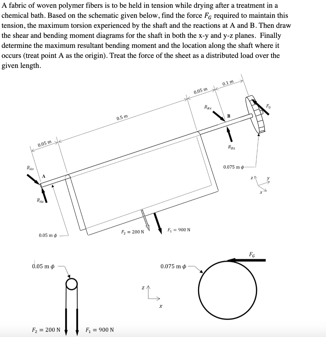

Transcribed Image Text:A fabric of woven polymer fibers is to be held in tension while drying after a treatment in a
chemical bath. Based on the schematic given below, find the force FG required to maintain this
tension, the maximum torsion experienced by the shaft and the reactions at A and B. Then draw
the shear and bending moment diagrams for the shaft in both the x-y and y-z planes. Finally
determine the maximum resultant bending moment and the location along the shaft where it
occurs (treat point A as the origin). Treat the force of the sheet as a distributed load over the
given length.
0.1 m
0.05 m
0.5 m
FG
0.05 m
F₂ = 200 N
RAX
4
RAZ
0.05 m p
0.05 m p
F₂ = 200 N
F₁ = 900 N
Z
F₁ = 900 N
0.075 m
x
RBX
B
RB₂
0.075 m p
FG
Expert Solution
This question has been solved!
Explore an expertly crafted, step-by-step solution for a thorough understanding of key concepts.

This is a popular solution

Trending nowThis is a popular solution!

Step by stepSolved in 4 steps with 6 images

Knowledge Booster


Learn more about
Need a deep-dive on the concept behind this application? Look no further. Learn more about this topic, mechanical-engineering and related others by exploring similar questions and additional content below.Similar questions
- For the beam shown, the magnitude of the distributed load is wo = 11.8 kN/m and the beam length is L = 7.9 m. (a) derive equations for the shear force Vand the bending moment M for any location in the beam. Place the origin at point A. (b) use the derived functions to plot the shear-force and bending-moment diagrams for the beam. Use your diagrams to determine the maximum shear force and maximum bending moment. Note that answers may be positive or negative. Here, "maximum" refers to the largest magnitude value, but you should enter your shear force and bending moment with the correct sign, using the sign convention presented in Section 7.2 of the textbook. If the magnitudes of the largest positive and largest negative values are the same, enter a positive number. Wo A В L. Answer: Vmax = kN Mmax kN•marrow_forwardA cantilevered beam is loaded with a uniformly distributed load as shown below. If w1 = 2000 lb/ft, what is the value of the moment (ft-lb) at x = 2 ft?(NEED NEAT HANDWRITTEN SOLUTION ONLY OTHERWISE DOWNVOTE)arrow_forwardDetermine the maximum positive normal bending stress that occurs in member ABC of the engine crane given the following information: Engine weight = 1500 lb Member ABC height (vertical cross sectional dimension) = 7 in Member ABC width (horizontal cross sectional dimension) = 1 in Express your answer to the nearest whole psi value. In your work, draw the shear and moment diagram for member ABC. For the question above, determine the maximum shear stress in member ABC that occurs between points A and B. Express your answer using the nearest whole psi value.arrow_forward
- I keep getting stuck on the moment diagram for this problem. How do I solve it?arrow_forwardA fixed beam of length 3 m is subjected to the distributed load shown above. (A) state the reaction forces at A and C (B) Write the equations for bending moment and shear force at any section along the beam and draw the shear force and bending moment diagram. (C) State the maximal bending moment and shear force and their locations.arrow_forwardQUESTION 1 Determine the reaction moment at x = 0 in kN-m. QUESTION 2 Determine the vertical reaction force at x = 0 in kN. QUESTION 3 (1-3) Determine the horizontal reaction force at x = 0 in kN. The distributed load, f(x), is equal to 100 kN/m. /// f(x) 3 marrow_forward
- An extruded polymer beam is subjected to a bending moment M. The length of the beam is L = 620 mm. The cross-sectional dimensions of the beam are b₁ = 39 mm, d₁ = 94 mm, b₂ = 23 mm, d₂ = 23 mm, and a = 8 mm. For this material, the allowable tensile bending stress is 17 MPa, and the allowable compressive bending stress is 11 MPa. Determine the largest moment M that can be applied as shown to the beam. ak a ↓ a M B A Answer: M = i L N•m b₁arrow_forwardde The beam shown supports a load that varies uniformly from 250 N/m at the left end to 0 N/m at the right end. The lengths of the beam segments are d₁=2 m, d₂ = 2 m, and d₂ = 8 m. Reactions Determine the reactions at pin A and roller C. Let positive values indicate upward forces. A= C= Internal Load Determine the internal shear and bending moment at a section passing through point D. Use the standard convention for the meaning of positive shears and bending moments. VD= Mp=arrow_forwardFor the beam shown in the figure, Calculate the support reaction forces and find the internal forces and moments at a point located 2 m from the right support and then draw the shear and moment diagram for this beam.arrow_forward
- Find the internal forces and moment acting at point B in the beam that weighs 15 kN. The cable tension is 6 kN. Clearly show your FBD and equations used. B 30° -0.3 m+ W=15 kN 0.6 m 0.6 m-arrow_forwardUse the graphical method to construct the shear-force and bending-moment diagrams for the beam shown. Label all significant points on each diagram and identify the maximum moments along with their respective locations. Additionally: Let a = 3.1 m, b = 5.9 m, w = 34 kN/m, P = 48 kN, Q = 34 kN, and Mc = 155 kN-m. Construct the shear-force and bending-moment diagrams P A В E Mc a b a а Determine the shear force acting at each of the following locations: (a)x = 3.1 – m (i.e., just to the left of support B) (b) x = 3.1 + m (i.e., just to the right of support B) (c)x = 12.1 – m (i.e., just to the left of support D) (d) x = 12.1 + m (i.e., just to the right of support D)arrow_forwardDraw a FBD of section CD. Do not solve the rest of the problemarrow_forward
arrow_back_ios
SEE MORE QUESTIONS
arrow_forward_ios
Recommended textbooks for you
- Elements Of ElectromagneticsMechanical EngineeringISBN:9780190698614Author:Sadiku, Matthew N. O.Publisher:Oxford University Press
 Mechanics of Materials (10th Edition)Mechanical EngineeringISBN:9780134319650Author:Russell C. HibbelerPublisher:PEARSON
 Thermodynamics: An Engineering ApproachMechanical EngineeringISBN:9781259822674Author:Yunus A. Cengel Dr., Michael A. BolesPublisher:McGraw-Hill Education
  Control Systems EngineeringMechanical EngineeringISBN:9781118170519Author:Norman S. NisePublisher:WILEY
 Mechanics of Materials (MindTap Course List)Mechanical EngineeringISBN:9781337093347Author:Barry J. Goodno, James M. GerePublisher:Cengage Learning
 Engineering Mechanics: StaticsMechanical EngineeringISBN:9781118807330Author:James L. Meriam, L. G. Kraige, J. N. BoltonPublisher:WILEY
Elements Of Electromagnetics
Mechanical Engineering
ISBN:9780190698614
Author:Sadiku, Matthew N. O.
Publisher:Oxford University Press
Mechanics of Materials (10th Edition)
Mechanical Engineering
ISBN:9780134319650
Author:Russell C. Hibbeler
Publisher:PEARSON
Thermodynamics: An Engineering Approach
Mechanical Engineering
ISBN:9781259822674
Author:Yunus A. Cengel Dr., Michael A. Boles
Publisher:McGraw-Hill Education
Control Systems Engineering
Mechanical Engineering
ISBN:9781118170519
Author:Norman S. Nise
Publisher:WILEY
Mechanics of Materials (MindTap Course List)
Mechanical Engineering
ISBN:9781337093347
Author:Barry J. Goodno, James M. Gere
Publisher:Cengage Learning
Engineering Mechanics: Statics
Mechanical Engineering
ISBN:9781118807330
Author:James L. Meriam, L. G. Kraige, J. N. Bolton
Publisher:WILEY